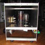
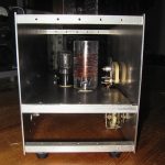
Here I want to show you my regenerative receiver:
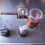
It uses two 12AH7 double triode tubes. They just happened to be available in my junk box.
Here is the schematic: Regen.pdf
The first two triodes are connected in series, so that they act as a synthetic tetrode. This „cascode“ configuration was discussed in detail by David Newkirk on his excellent website.
The detector circuit presented here was originally used in a receiver that was lent to me by a fellow ham in 1968 when I just started my amateur radio career. It was a kit sold by a German company (Technik-Versand Bremen) and worked perfectly well in those days even on the 10 meter band. I always regretted having given it back so, I wanted to build a replica now. This works even better than the original.
Regeneration is controlled by adjusting the voltage of the second triode’s grid. When the regeneration control is at its minimum position, that means we have 0 Volts at pin 5, there is also no anode voltage at pin 3. The voltage at pin 6 is at its maximum then. When the regeneration control is engaged (voltage at pin 5 increases) the voltage at pin 3 also rises up. At the same time the voltage at pin 6 decreases, because the tube is drawing current and there is a drop across the 100k resistor.
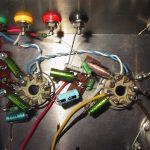
The second 12AH7 works as a two stage audio amplifier. I tried to reduce the number of components to a minimum so, there is no cathode RC-combination in the audio stages. The necessary negative bias voltages are produced by the small grid currents flowing through the 10 MOhm grid resistors (grid leak bias). With my 10 MOhm VTVM I can measure about -0.65 Volts at the grids so, the actual voltage should be about -1.3 Volts. There is no noticeable distortion of the audio signal.
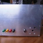
The coupling capacitors in front of the grids are quite small. This helps to reduce the hum. I tried an output transformer in an earlier version (you can still see the slots on the chassis where it was mounted). I hoped to get more audio output this way. But this was a disappointment. So, it was replaced with the original RC-combination (25k/.68µ) shown in the diagram with no ill effects. I can use high and low impedance headphones with good volume. The low impedance ones sound much more „bassy“.
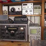
The receiver is very sensitive compared to the pentode circuits I tried before. Using a two feet test lead as an antenna it hears everything on 40m that the R-388 does. Of course, the selectivity is not comparable. But in most cases this is no problem (the selectivity is between the ears of the operator ;-)). Regeneration control is very smooth without any noticeable frequency pulling or hysteresis. But, the regen needs a good ground. In my installation this is a connection to the heating pipe. My shack is located under the roof in the second floor. So, this ground connection is quite long and probably also acts as an antenna. Without this ground the receiver shows severe hand capacity effects and is difficult to tune.
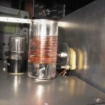
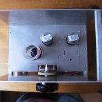
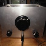
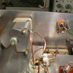
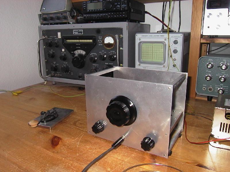
The big center knob drives the band-spread tuning cap. This cap is rather small. I had to remove most of the rotor plates to get a tuning range from 7.0 to 7.2 MHz. It rotates very smoothly and without using a reduction drive tuning in an SSB station is no problem at all. In the lower left you see the control for the band-set capacitor. The knob in the lower right drives the potentiometer for regeneration control.
The plug-in coil is tailored for the 40 meter band where we find a lot of active CW stations here in Germany. It has 18 turns (about 9 µH) with the tap at 5 turns from ground. This tap position needs some more experimentation. I will try to lower the tap to 3 turns so that oscillation starts at a slightly higher voltage at pin 5 of the second triode.
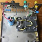
The power supply for my regen is mounted inside the box of a butchered PC supply. I ripped off everything and just kept the case, the AC input socket, the on-off switch and two 330µF electrolytic capacitors. The ‘ugly construction’ works flawlessly ;-). The B+ output delivers about 70 Volts. In spite of the simple circuit, this voltage is quite stable and clean because the receiver draws very little current (about 10mA). Rectification and stabilization of the heater voltage was applied to prevent any hum. The diode in the ground lead of the regulator raises the output voltage to exactly 12.6 volts. Later I added a bleeder resistor of 1 kOhm to the output which is not shown in the diagram.
Additional pictures: