The components for this transmitter had been laying around in my scrap box for almost 40 years. Now I thought it was time to build it.

The first time I came across this circuit was in 1961 when I read the book “Funkfernsteuerung für den Modellbauer”. This was a translation by H. Bruss and Hans-A. Pfeil of the English title “Simple Radio-Control” by H. G. Hundleby. The circuit was called the “Aeromodeller Transmitter” and was a free running oscillator without a crystal. I found the adaption to crystal control in the German book “Drahtlose Fernsteuerung von Flugmodellen” (Radio Control of Model Aircraft) by Karl Schultheiss, DL1QK.
After looking at the circuit diagrams offered on the ‘Glowbugs’ server I realized that this actually was a Jones transmitter. But there was no reference made to the Jones circuit in the above mentioned publications.
See the circuit diagram here: jones.pdf
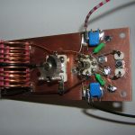
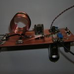
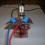
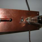
The transmitter is built on a piece of two sided copper-clad epoxy board. The bottom layer serves as a ground plane. Connections are soldered on islands (abt ½” squared) made of the same material glued to the surface. The coil has 12 turns of No. 16 copper wire. The diameter is abt 1″ and the length abt 1¼”. It was wound over a wooden dowel and fixed with three pieces of fiber glass rod (from a kite shop). The antenna coupling coil is one turn of insulated stranded wire wound over the center of the plate coil. The choke has 25µH.
For the first test I used the power supply of my regen. With only 70 volts on the plates the power input was quite low (only 350 mW). Stability was good but, it chirped heavily. The chirp was reduced when I tuned the plate circuit more to the high frequency side and not to the lowest dip.
At school I had the opportunity to connect the transmitter to a spectrum analyzer. When the plate circuit was tuned to the lowest dip, it produced a lot of harmonics. The odd harmonics were only 15 to 20 dB down from the fundamental and the even harmonics abt 30 to 40 dB. It was interesting to detune the plate circuit to the high frequency side until oscillation stopped, and then go back slowly to resonance. I stopped at the point where oscillation just started again (not yet at the lowest dip). Now the signal was very clean. You could only see the fundamental. The harmonics were in the noise!
This transmitter was built only for experimentation. Now I have gained enough experience to start a real project, a 40 meter Jones TX. It will use a 6Z7G tube (I like the symmetrical pin-out) and a rock I obtained from Bry, AF4K.
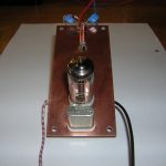
Additional pictures: