Toothpick
This is the story of how I designed and built the second version of my glider “Toothpick”.
I flew the original version at competitions in 1988 and 1989. The special thing about this model was the very high aspect ratio of the wings.
I already published some data about this model in a previous post. (Contest Flying)
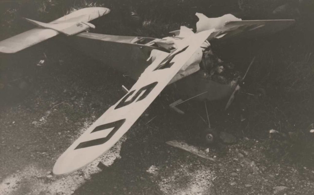
I was very satisfied with the flight performance at the time. Unfortunately, in 1990, I had a collision with a model of my friend Frank Neumann while flying slopes. My “Toothpick” was completely destroyed.
Very soon I made plans for a successor.
I built a new pair of wings out of Styrofoam and Abachi veneer.
Luckily Christoph Sarter still had the negative mold for the fuselage, so we were able to laminate a new one together.
Since I was very stressed by my job as a teacher in 1990, I had to interrupt my work on this model, and provisionally stored the half-finished parts.
In 1994 I joined a group of model pilots who flew F3B competitions. We started working together to make negative molds for our own F3B model. I forgot about my “Toothpick” project because I thought it was no longer competitive anyhow.
After we held a meeting of senior RC-4 competition pilots in 2022, (I reported about it in my “Phoebus” post), I remembered the old parts of my “Toothpick”. They were still lying around in my basement and had survived my two moves to new apartments in relatively good condition. Now I thought it was time to finish the construction.
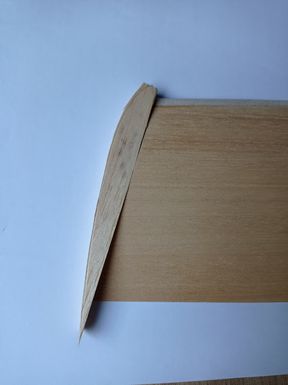
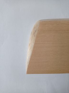
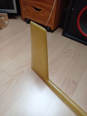
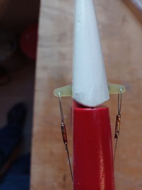
The leading edges of the wings were sanded to shape and the wing tips were finished.
Root ribs were prepared and glued to the fuselage.
The gaps were filled and smoothed.
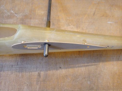
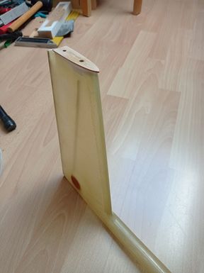
The support for the horizontal stabilizer was adapted to the vertical stab.
Before…
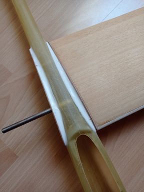
And after…
Rudder and horizontal stab were made.
The ailerons were cut out and adjusted. The corresponding servos and push rods were installed.
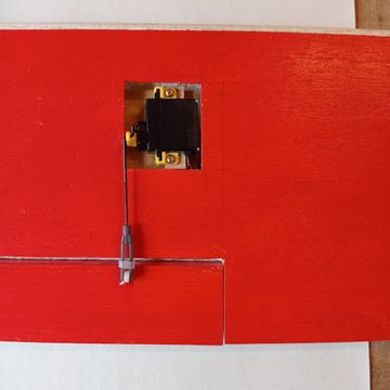
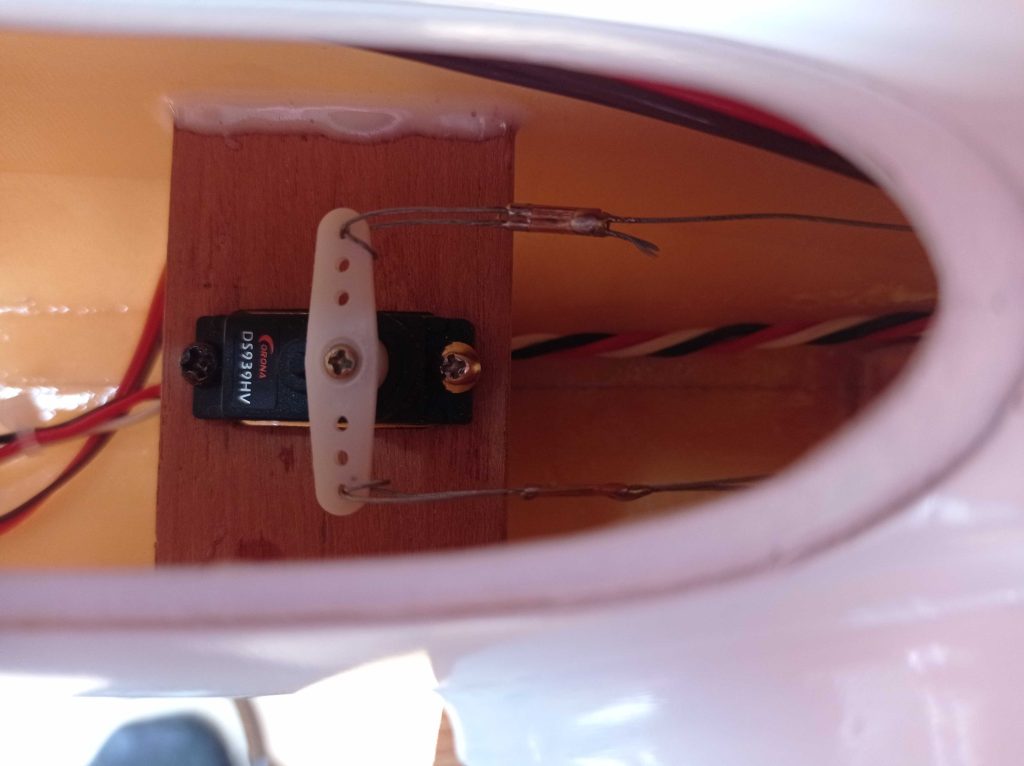
The servos for rudder and elevator, the receiver and the battery were installed.
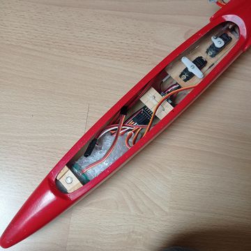
The rudder is operated with litz wire, which dates back to when I was building control line models.
The hatch cover is fastened with a magnet.
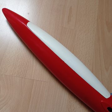
Here you see the finished product.
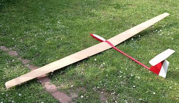
The maiden flight was on April 6, 2024. It flies! But I realized that the center of gravity needed to be moved further forward.
The Phoebus Project
There was a special reason to start this project. I had not flown any contests since 2001. On October 7th 2021 Marc Schneider initiated a WhatsApp group called “RC4-E” and invited pilots to this group who had flown this class in the 80s and 90s of the last century. The idea was to organize a meeting and to fly a contest to the original rules just for fun. More and more participants in the competitions of that time found out about this group and became part of it. In the end the group had 12 members. Everyone was very enthusiastic about this idea and proudly showed their models that they wanted to participate with.
Now my problem became obvious: All my models that I had used in those contests were either damaged or in very bad shape. The only solution was: I had to build something new. The scheduled time for the meeting was late May 2022, so I should have plenty of time to build a new model.
I first went down to my workshop in the cellar to find out what material was still there. Balsa wood and plywood in various thicknesses and pine strips were available in sufficient quantities.
Then I found the pod and boom for a fuselage which were given to me by Enrico Vettermann in 1990. They were still waiting for a good use.
In the same year I had produced a pair of rib blocks for my father as a gift for his 69th birthday. Sadly, my father died in January 1991 and could not make use of them any more. The ribs were still laying around in my workshop in a plastic bag in perfect condition. I decided to use them now for my new model.
The airfoil was a Clark-Y with reduced thickness of 10 percent.
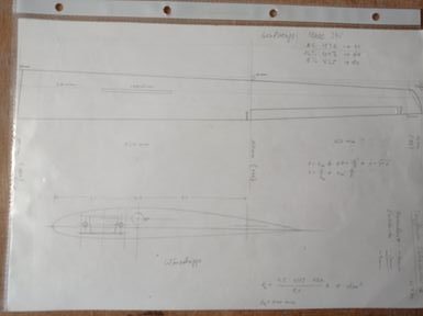
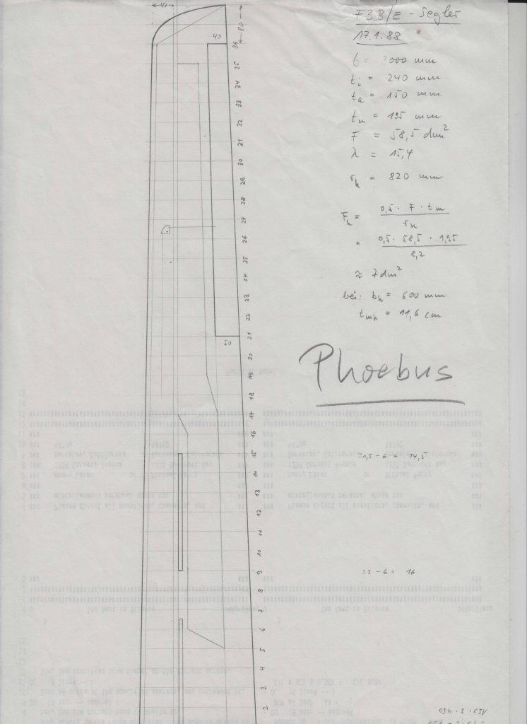
In January 1988 I had already made a rough scaled down drawing of a wing that should be suitable for my new design. The intended span should be about 3000mm (~118″), the root chord 240mm (~9.5″) and the tip chord 150mm (~6″). That should result in a wing area of about 58.5 dm2 (~907 in2) and an aspect ratio of 15.4. The wing should only be partly planked to save weight. At the end I wanted to reach a total weight of the model of well under 2kg.
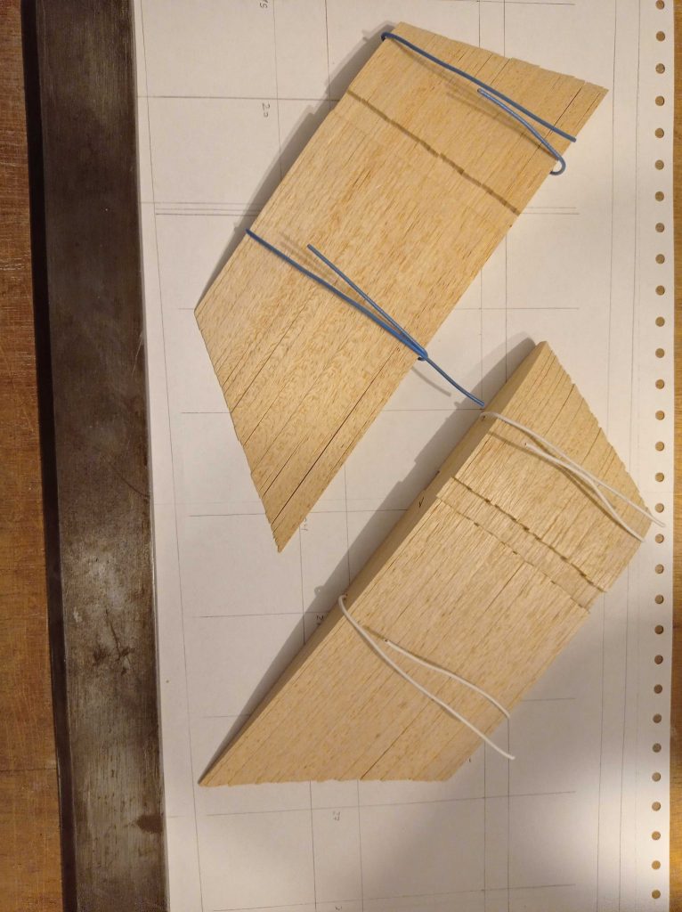
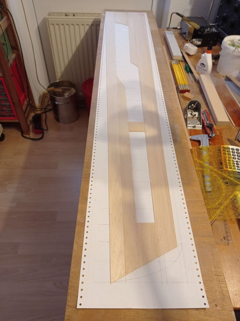
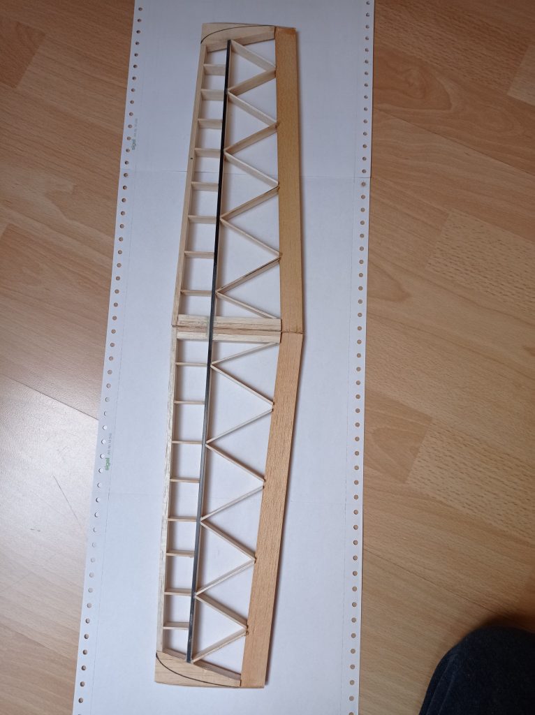
I made a drawing of the right wing in original size. Fortunately, I had a lot of old endless printing paper that was very suitable for this. To start building, I glued together the lower skin of the wing (balsa 1.5mm; ~1/16″).
After that I glued on the lower spar (pine 10mm x 3mm; ~8/20″ x 1/8″) and the ribs (balsa 2mm; ~1/12″).
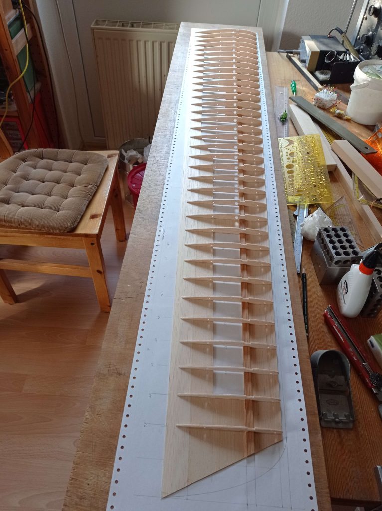
After gluing in the webs between the ribs (balsa 3mm; ~1/8″; vertical grain)…
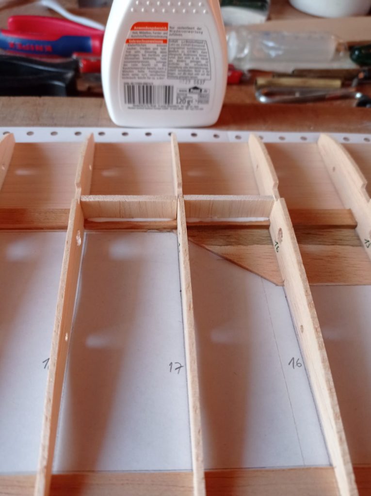
…the upper spar could be added.
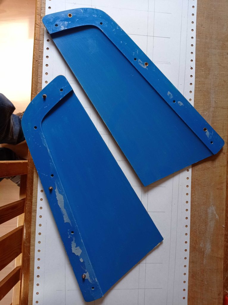
In a hidden box in the farthest corner of my workshop I found a pair of spoilers that I had salvaged from an older crashed model. They fitted nicely into my new wings.
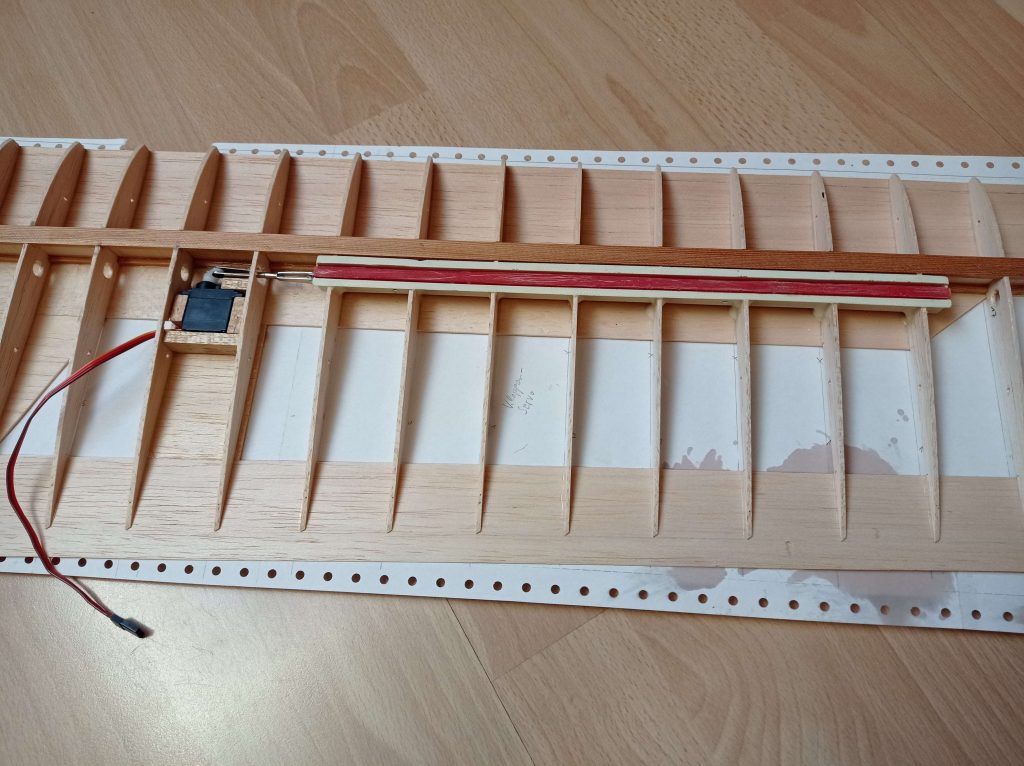
The spoiler servo was permanently glued to the bottom skin between two of the ribs. I used Corona DS939HV servos in all locations.
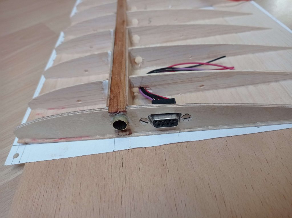
The webbing between the first four ribs was made of plywood to withstand the strong forces in this area. The wings should be attached to the fuselage with a round steel rod (8mm diameter; ~1/3″). For this I glued brass tubes between the spars at an angle of 3.5 degrees to get the right dihedral for the wings. The cavities were filled with epoxy. A Sub-D socket was attached to the first rib for the electrical connections to the servos.
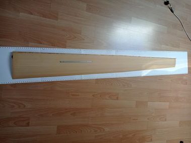
After completing the wiring, the top planking and the rib caps could be glued on.
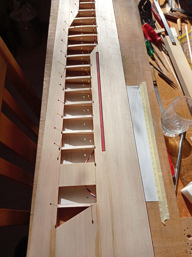
The leading edge and wing tip block were attached and the ailerons were cut out.
As I did not have enough space in my workshop to build both wings simultaneously, the left wing was made afterwards.
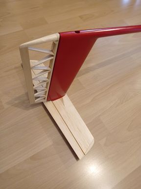
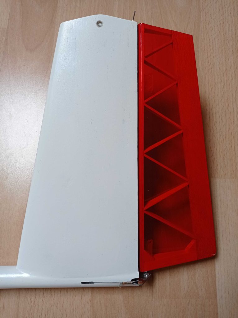
Now I made a drawing for the horizontal stabilizer of the t-tail. Depending on the length of the fuselage (distance between the wing and the stab), I calculated the area of the stab at 7 dm2 (108 in2). A grid of square ribs and a spar were glued together. The narrow spacing of the ribs in the front should prevent sagging in of the skin and the zig-zag arrangement of the ribs in the back should prevent twisting of the stab. The spar was reinforced by a carbon fiber rod.
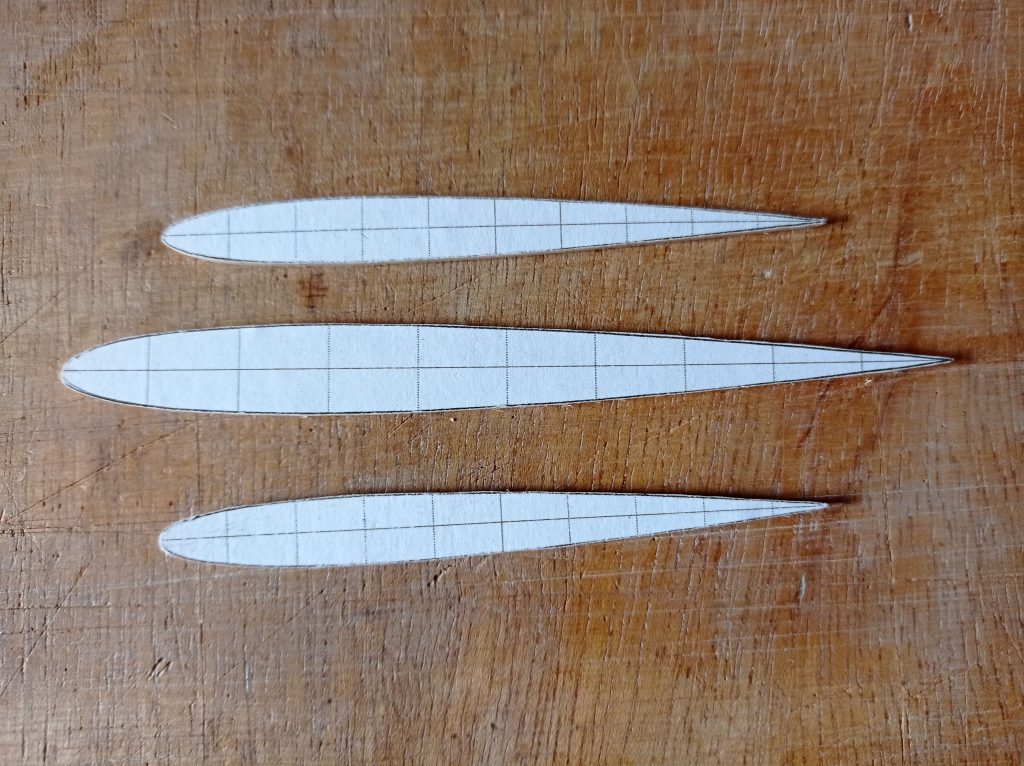
Symmetrical airfoil ribs made of plywood (NACA 0010) were attached and the complete structure was sanded to the right shape.
Into the underside of the tailplane I glued kind of a hinge consisting of a short piece of brass tube and a steel pin.
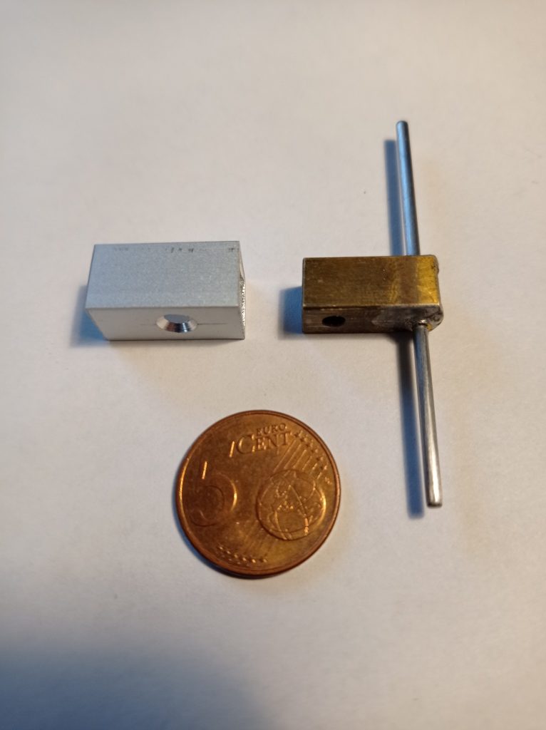
The short aluminum tube was later glued into the top of the vertical stabilizer, where the brass tube is fastened with a small 3mm (M3) screw.
First I wanted to laminate the vertical stabilizer with fiberglass into a mold that I had received from Horst Baum many years ago.
Unfortunately, because of my lack of experience and because I didn’t have a good vacuum pump, this wasn’t successful.
So I decided, to build the vertical stabilizer in rib and plank construction from balsa wood. The skin (balsa 1mm; ~1/24″) was reinforced inside and outside with very light glass cloth. The servo for the horizontal stab was permanently glued inside. The next picture shows the completed vertical stab, including the rudder, glued to the fishing rod boom of the fuselage. The thin wire hook extruding from the top is the end of the push rod coming from the servo.
The rudder is operated via two thin control line wires by the only one servo needed inside the fuselage pod.
Approximately 200g (7 oz) of lead shot had to be glued firmly into the nose of the fuselage to achieve the correct center of gravity.
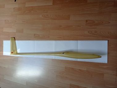
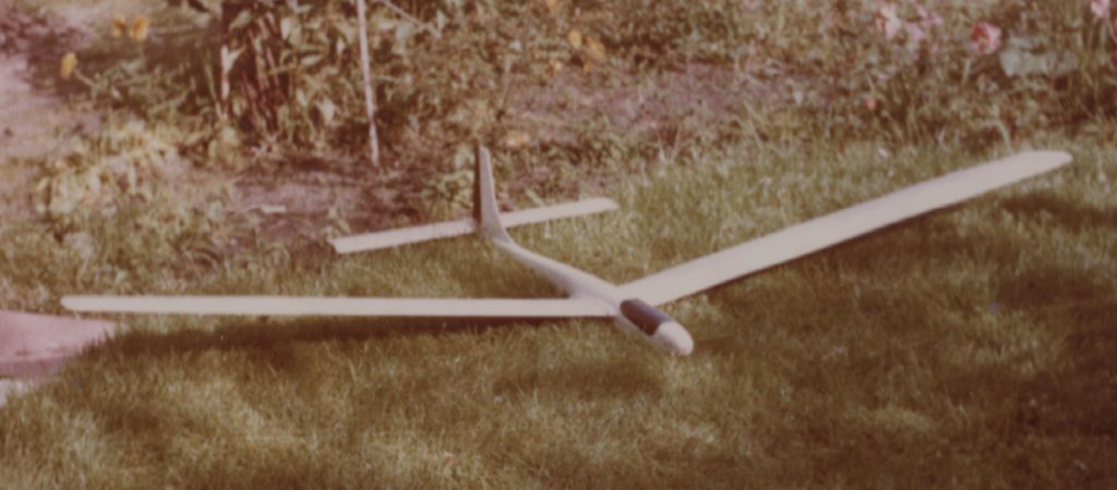
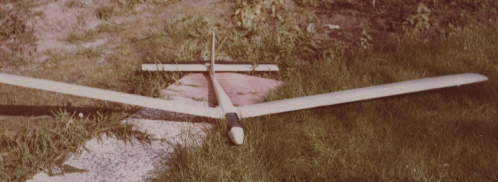
The next picture shows the finished model in my garden.
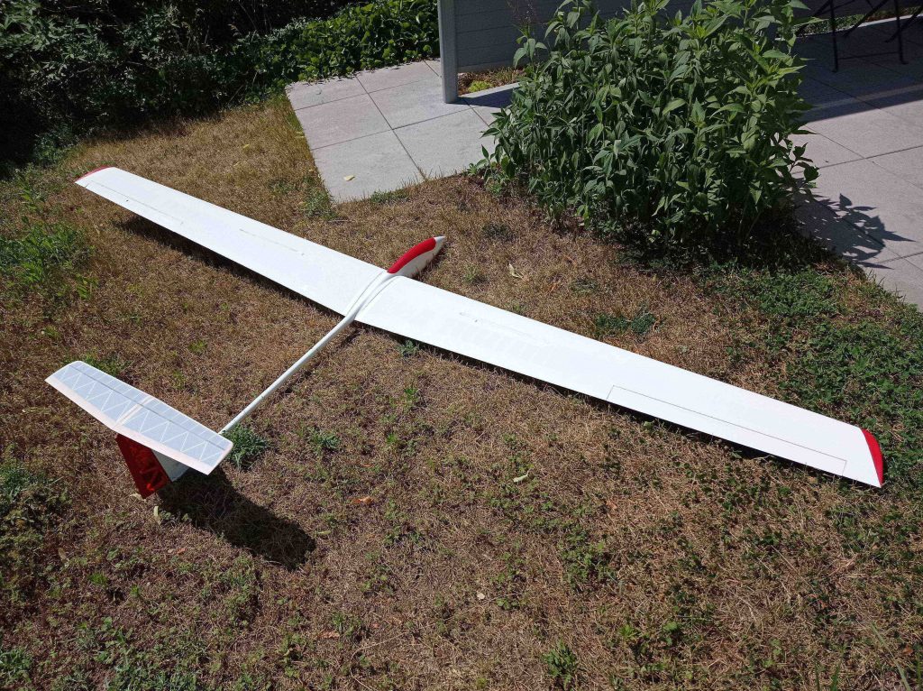
It came out at a total weight of 1600g (56.5 oz).
I finished the model only five days before the planned meeting at the Hesselberg. Therefor I did not have the chance to fly it in at home. This would have to be done directly on the mountain.
When my wife and I arrived there, I was overjoyed to meet and greet seven other pilots and their wives. Unfortunately the weather was bad and the strong wind was coming from the wrong direction. Therefor slope soaring was not possible. I did not want to risk my model in such miserable conditions anyhow.
We decided to meet meet again the next day at the local model flying club’s airfield at the foot of the mountain, hoping for better conditions. We didn’t really have a competition, we decided to just have fun and fly as much as possible. With foresight, I had packed my high start towline at home. Joachim Regel also brought one and Christoph Sarter installed his F3B winch.
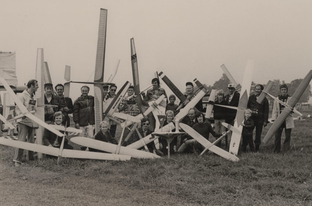
The next picture shows our group on the Grueb airfield presenting our models:
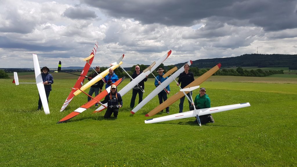
The pilots in the back from left to right are: Me, Stephan Laemmlein, Enrico Vettermann, Frank Neumann, Gerhard Schmidt and Christoph Sarter. Kneeling in the front are Marc Schneider and Joachim Regel. The Hesselberg is visible in the background.
Now my model was flown in successfully and I’m very happy with the result.
In the meantime I have tested the model a lot on the local flying field of the Sportfliegerclub Darmstadt near Messel. The original CG had not to be changed. During the high start the model climbs steeply without any risk of breaking out. When circling in the thermals I realized that a lot of rudder control is needed. The dihedral of the wings is quite high (3.5 degrees per side). So, very little aileron control is necessary. The model seems to dive into the circle easily and needs a lot of up elevator. But that could just be a matter of getting used to it. Maybe, the horizontal stabilizer could be a little bigger. I made some rolls, both against the wind and with tailwind. That worked out well, but the rolling rate was quite slow. So, it is definitely no aerobatic model, and that was not my intention.
Local Club Activity
From the seventies to the early eighties I was a member of the Elmshorner Modellbau Club.
Almost every year a gliding contest was held with many participants who were all members of the club:
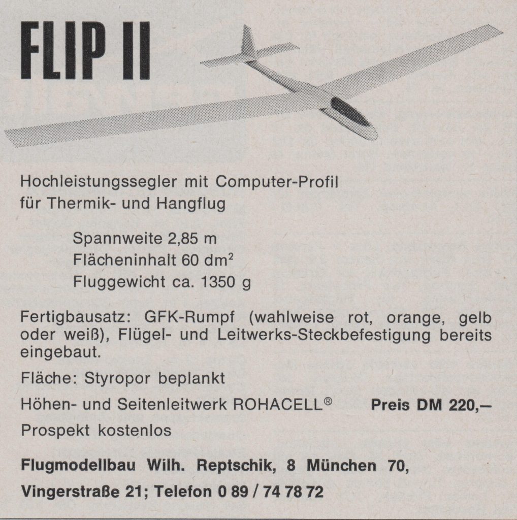
You see me kneeling in the foreground on the left. My model is a FLIP II that I built from a kit. Here is the manufacturer’s ad from 1973:
My father is holding the model with the largest wingspan. He always loved big models.
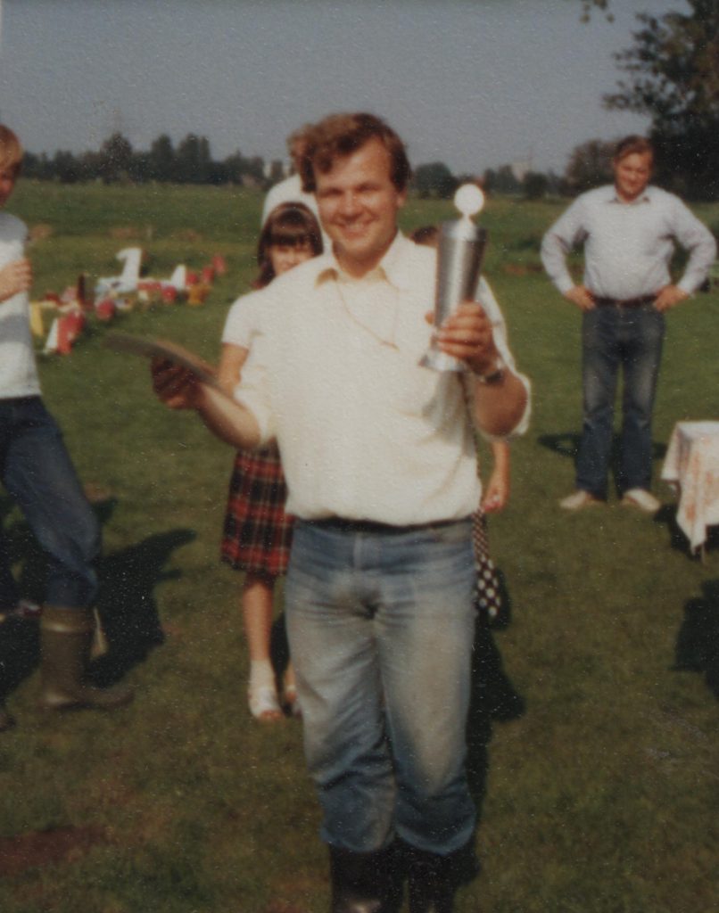
I’ve won the trophy for several years:
The next picture shows me in a deck chair during a one hour flight with my FLIP II:
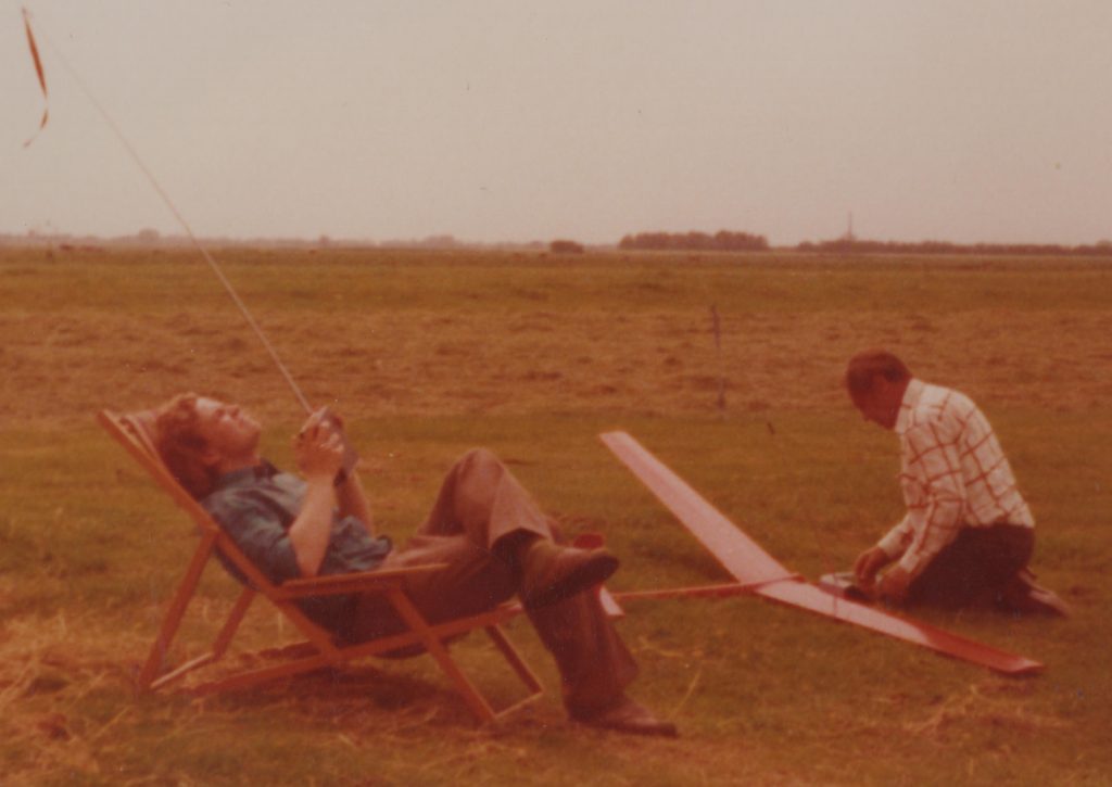
My father is preparing his DRANA sailplane. This was a design of Erich Dreessen from Neumuenster. We bought several fiberglass fuselages from him and added our own wings. Erich also sold very high quality balsa wood.
The next picture shows me in 1981 with a model that I built using a SPRINT fuselage by Erich Dreessen:
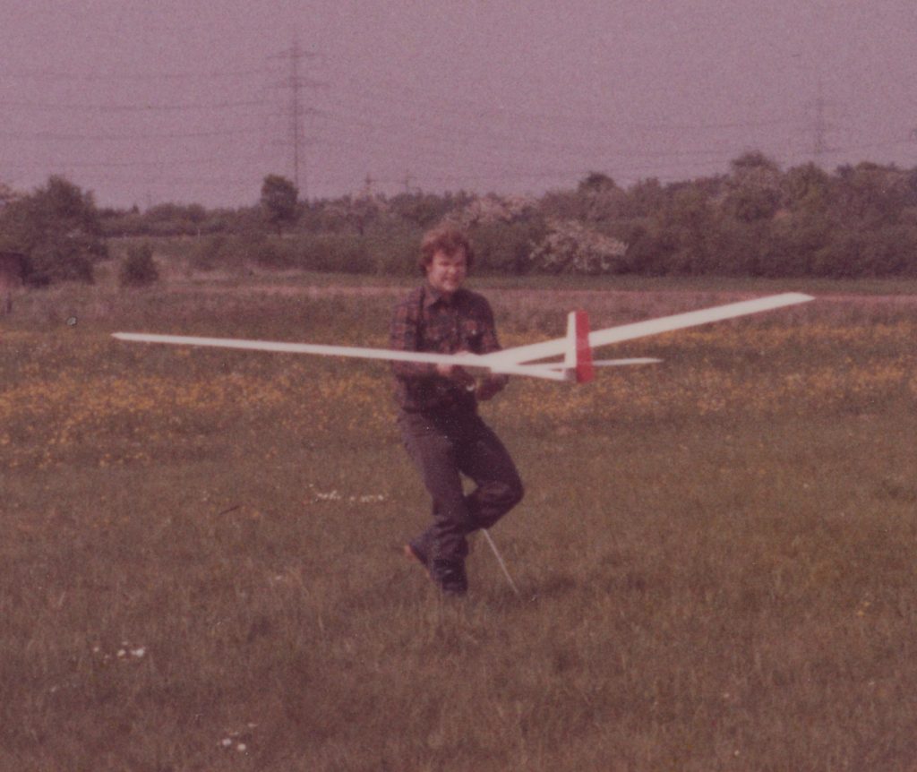
I built the wings with a span of 3.2 meters and a root chord of 27 centimeters. The performance was excellent. I lost the model in Frankfurt when I started it with a broken receiver antenna and lost control.
Here you see another picture of my SPRINT laying in the preparation area of the Elmshorn flying field:
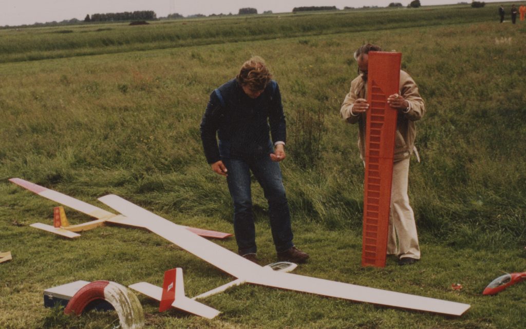
My father is holding the wings of his latest DRANA.
Contest Flying
In 1977 I went to Darmstadt to start my studies of electricity and mathematics at the “Technische Hochschule“. Soon I became a member of the “Sportfliegerclub Darmstadt“. Those pilots were very active in contest flying. The most flown class was F3B/E for model gliders. The task was to fly for exactly 200 seconds after a high start with a fishing line of 100 meters length (hand towing, no winches, no rubber). You had to land in the center of a circle of 15 meters diameter. The elegance of the landing approach was also rated. This means that the model had to fly straight for at least 10 seconds, sink evenly and touch down gently without bumping or turning. This was practically only possible if the model had ailerons and spoilers.
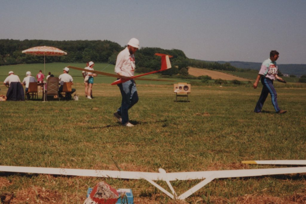
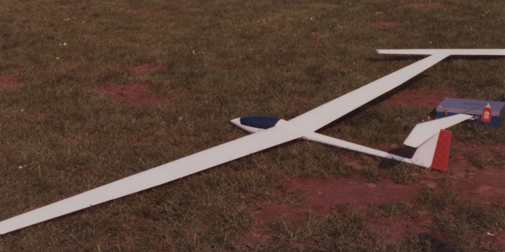
The next picture shows me as a participant of a Hessian F3B/E contest in 1989 in Braunfels, bringing my model back to the preparation area after landing:
From my head-down posture, you can imagine that the flight wasn’t too successful (grin).
Here is another view of my model:
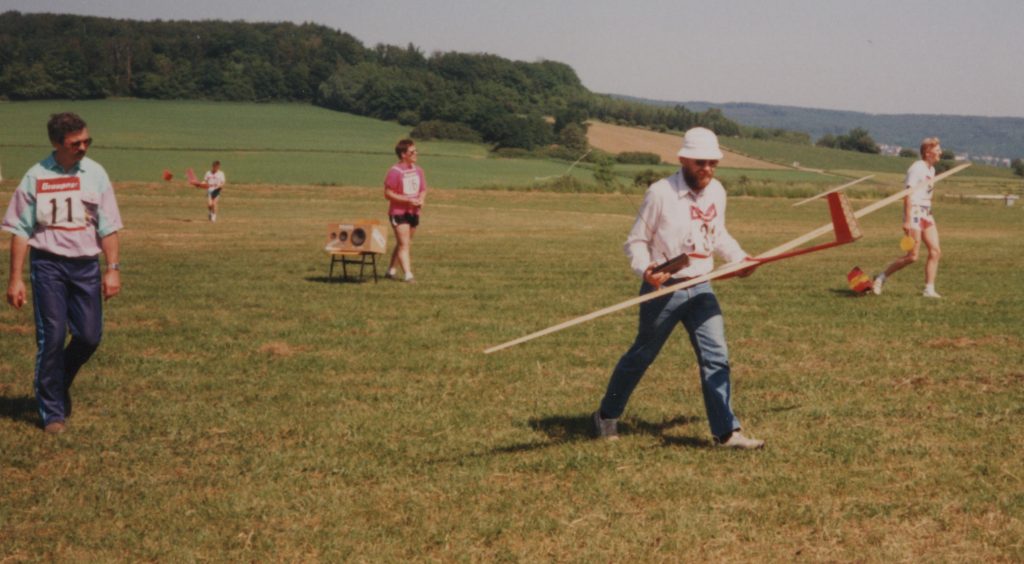
The man with the number 11 is Horst Baum, who assisted me on this flight. He is an excellent pilot and model builder (better than me).
P.S.: Regrettably, Horst Baum died on February 4, 2024. RIP
The model is my own design with a fiberglass fuselage made by Christoph Sarter. It has 3.2 meters wingspan and weights 1.8 kg. The wings have a high aspect ratio, with a root chord of 180mm and a tip chord of 90mm. The root airfoil is a semi symmetrical RITZ 2-30-12 (for mechanical strength) and the airfoil of the outer third of the wing is a CLARK-Y, thinned down to 10 percent . This sounds a little strange for a thermal flyer. But the performance is very good, especially in windy conditions. I cut the cores for the foam wings in the workshop of Hermann Fading.
Slope Flying
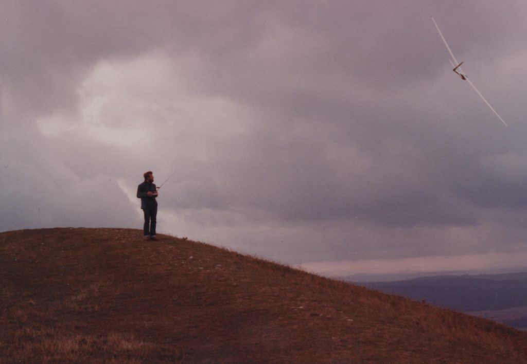
In the late seventies and the early eighties my father and I were very active in slope flying. So far we only knew the Wasserkuppe in the Rhön as an important slope flying area. And only from the stories of other model pilots, because we had never been there before. Then we accidentally discovered the Hesselberg in Franken (Northern Bavaria). We found accommodation in the Rötter brewery close to the mountain in Gerolfingen. We spent our summer holidays there for several years. The picture shows me standing on top of the mountain flying one of my models:
Almost every year another model pilot spent his vacation time there, who became very important for the development of my hobby. His name is Hermann Fading. His models (always his own designs) are superbly built and he is a master at locating thermals. From him I really learned thermal flying. In the following years I spent many days in his workshop, where he showed me how to build wings from Styrofoam, glass fiber and Abachi veneer.
The next picture shows my SB-11 with 4.5 meters wingspan which was designed by Hermann:
I built the wings in his workshop because at that time I had no way of building models in my small student dorm.
My Model Flying History (1965)
1965: This year was very important for me. I designed and constructed two glider models. The first was quite a failure. It was built way too heavy and the wing had a constant chord, which was unfavorable. It didn’t fly very well and broke after only a few test flights. Unfortunately I don’t have any photos of this model. I received a lot of information from the experienced model pilots from Kaltenkirchen about the mistakes I had made with this model. Therefore, the next construction should be much better.
In the meantime, my friend Joachim Jürgensen had designed and built his own model. The special thing about it was that the wings were very much tapered. The root chord was 200mm and the chord of the tip was only 100mm. This model had a very good glide angle as long as it was flying straight ahead. As soon as you tried to make a turn, the inner wing tip stalled and the model began to spin. It was almost impossible to fly.
So it was clear to me that I had to find a better compromise here. My new wings got a root chord of 200mm and a tip chord of 150mm. In addition, over the last third of the half span the wing got a washout of about 2 degrees, in order to prevent the tip stall.
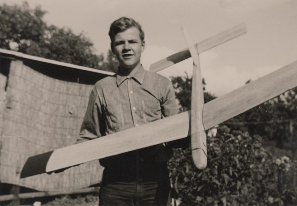
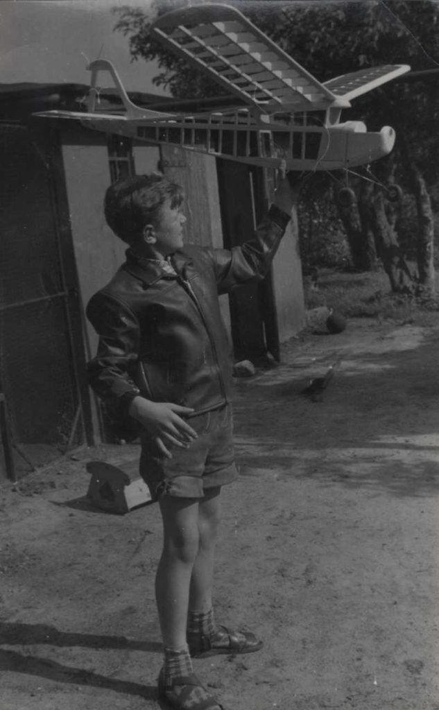
The picture shows me, holding the model. I published more information and more photos in another post.
My father had built another sailplane of his own design:
It was a bigger than mine (2500mm wingspan) and already had rudder and elevator control. We had built a new radio from kits offered by the “Reuter” company.
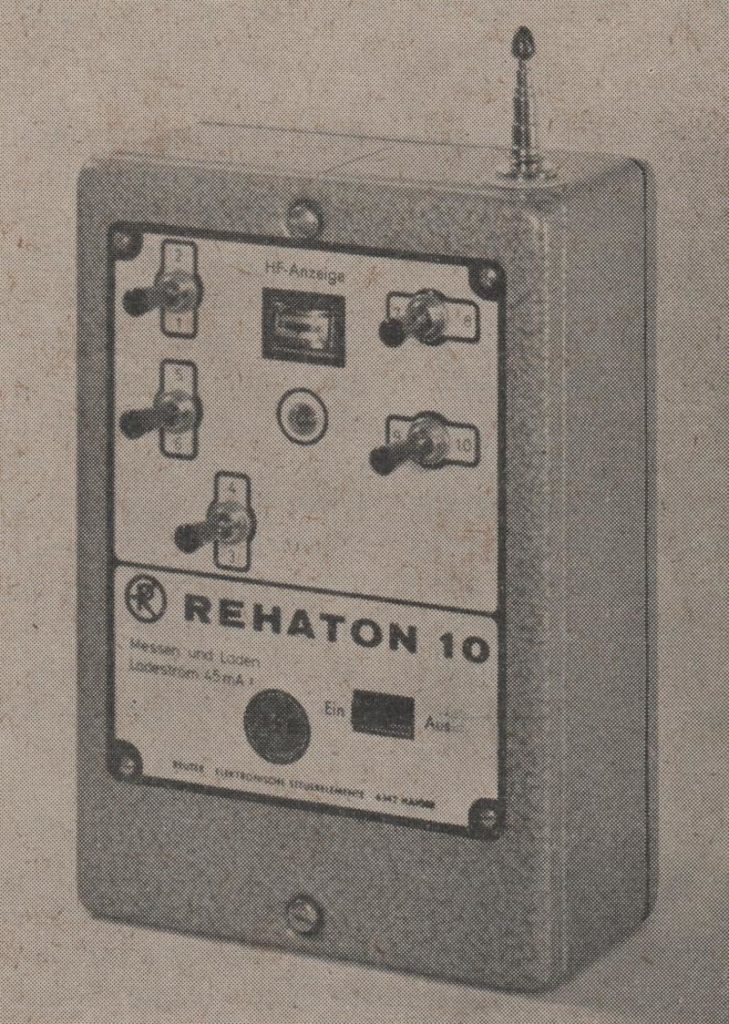
The picture shows the fully equipped 10-channel version of the transmitter. Ours only had 4 channels (two sticks).
My Model Flying History (1963)
1963: In the meantime, our interest in a powered radio-controlled model grew again. In the “Modell” magazine we saw the picture of the “Tele-Pilot”. It was a design of Heinz Siegle and offered by the “Engel-Modellbau” company (it no longer exists today). At the Vietzke model shop we found the “Engel”-catalog and we ordered the kit. Here is the page of a later catalog. The price was not too high. It was a bigger model with a 65 inch wingspan and a large dihedral. We were convinced that this model had to fly well. In our opinion this big plane needed a big engine. So, an OS-Max 29 with 5cc displacement was ordered.
Since our garage was now occupied by our car, it could no longer be used as our workshop. Fortunately we were able to free a corner in our cellar room and install a workbench there. When the kit arrived, we started the assembly in our new cellar workshop. It went together without any problems. The following picture shows the completed uncovered frame without radio and engine installed:

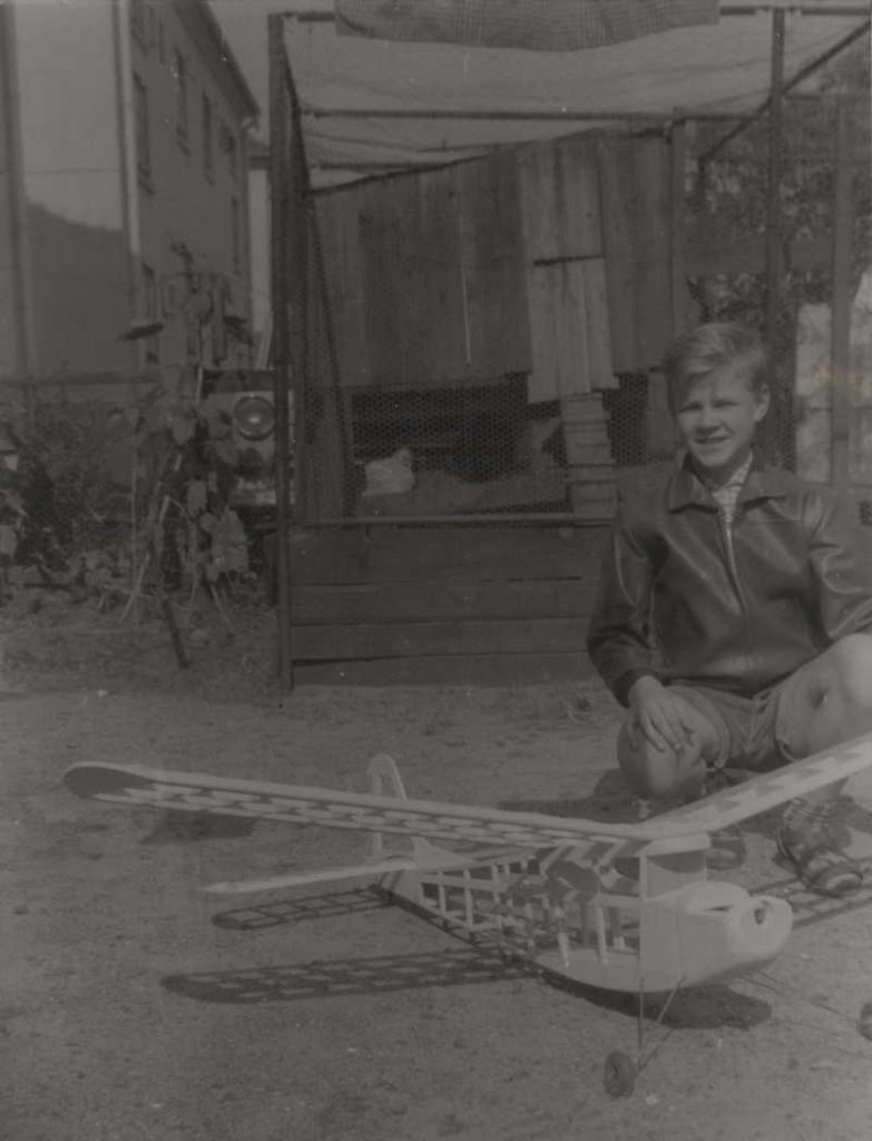
The next picture shows me presenting the frame in front of our chicken house:
The frame presented by me (wearing the famous Lederhosen) in the backyard of our house:
It was an impressive model for sure.
A few weeks later we proudly carried the model to our local grassland “airfield”. Of course there were some curious spectators again. We made some initial hand starts without the engine running. The model glided smoothly like a sailplane. The center of gravity and the longitudinal dihedral angle were obviously correct. We dared to try the first powered flight. The engine was started without any problems. We tested the radio (Metz-Mecatron) and it worked flawlessly. The engine could be throttled by the third channel of our radio. Push the button: engine idling. Push the button again: full speed. The next picture shows the model just prior to the first flight. I hold the transmitter, my father gives commands and the son of our neighbors, Holger Tamm, assists us.
I took over the transmitter, my father threw the model in the air. It went up straight, beautifully and evenly. It responded to the rudder instantly and so I let it make a big left turn. In very short time the model reached a height of about 100 meters. What a beautiful sight. When I thought that it was high enough I pushed the button for low engine throttle. That worked well and the engine slowed down. But even in this throttled down position, it still had so much power that our model continued to climb. Obviously we had too much engine power. Our OS-Max 15 would probably have been sufficient. But how should I get the model down now? We couldn’t let the model climb until it was finally out of sight.
The tank was still rather full and we had no elevator control. I got the idea that a spiral dive would be the right method to get the model down. So I gave full left rudder. The spiral began and the model quickly lost height. I put the rudder back on neutral to end the spiral but the model didn’t want to recover. It did not even react on full right rudder. The spiral continued. Eventually the model disappeared behind a house and could not be seen any more. We didn’t hear the crash but it was clear: the model hit the ground somewhere. Great horror! We quickly ran in the direction where we suspected the impact would be. Behind a couple of houses we eventually found the debris in a ditch between a front yard and the street.
In our opinion this was beyond any repair. With the experience I have today I would have repaired it. Despite the total loss, we were still rather lucky. The model could have hit the roof of a house or injured or killed a person.
In retrospect, it was also clear to me that our “airfield” in Elmshorn would have been too small anyway for an orderly landing approach. We decided to make our next attempts only in Kaltenkirchen.