Home » Ham Radio
Category Archives: Ham Radio
WSPR with Raspberry Pi
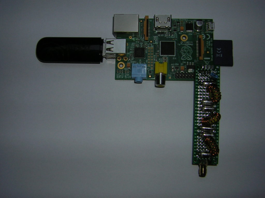
After my successful experiments with WSPR and FT8 on my FT-900, I wanted to try a low power stand alone beacon for WSPR. I happened to find an old Raspberry Pi in one of my bottomless drawers.
A search on the WEB revealed that there was a way to convert this board into a transmitter. Very inspiring instruction was found on a German website. The program called WsprryPi was downloaded from GitHub. The instructions for installation and usage on this site were very detailed and helpful.
I wanted to run the beacon autonomously without connecting another controlling PC. DL7VDX suggested to write a script which was started automatically on boot-up. I tried this, but had no real success. The easiest way was to add a command line to the /etc/rc.local file. This worked perfectly well.
The Raspi was connected to my local WLAN via a USB-stick, to receive a time signal from an NTP-server.
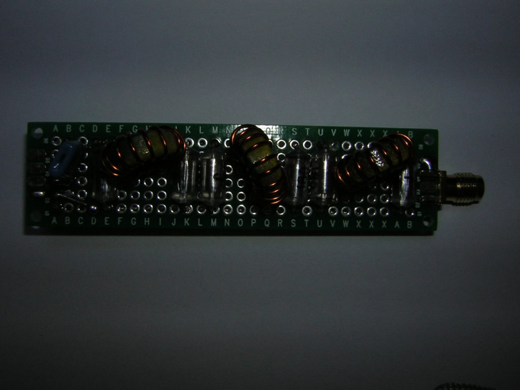
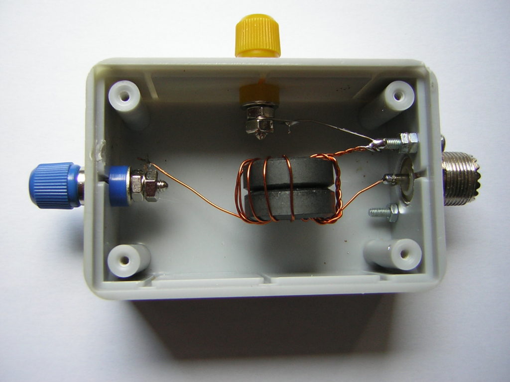
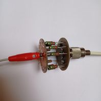
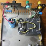
Very important: A low-pass filter had to be inserted between the output of the Pi and the antenna! I found detailed instruction for this on the QRP-Labs website. Fortunately, I had some AMIDON T-50-6 cores laying around. Three coils were wound with 0.6 mm magnet wire (~AWG 23). All the components were soldered to an experimental circuit board:
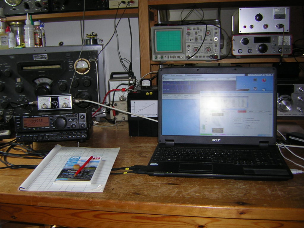
One problem was, to measure the filter’s frequency response. The only test equipment I had for this was my FA-VA5 antenna analyzer. I inserted the filter between this instrument and a 50-Ohm dummy load:
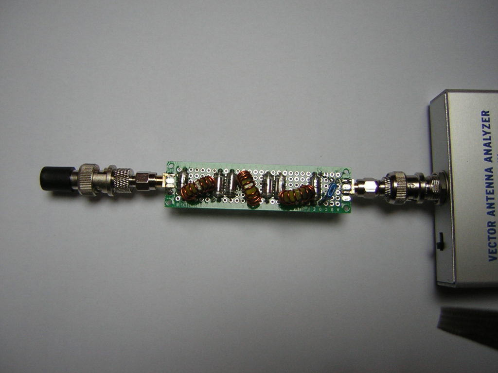
Then I scanned the Z-response . . .

. . . and SWR over frequency:
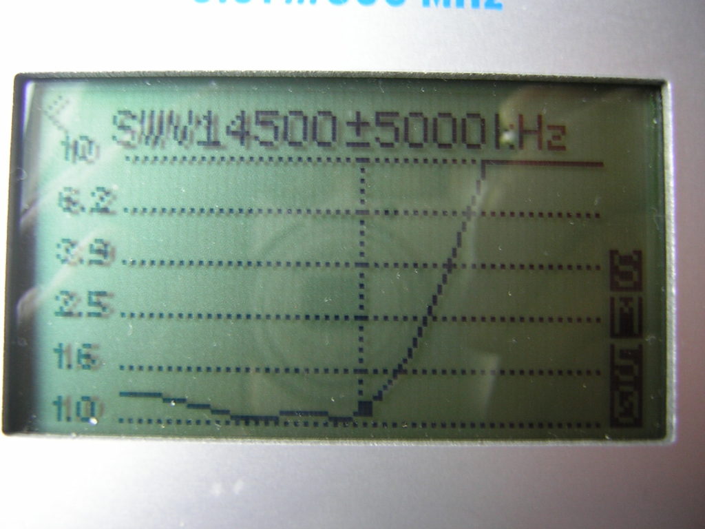
So, in my opinion, the quality of the filter was adequate.
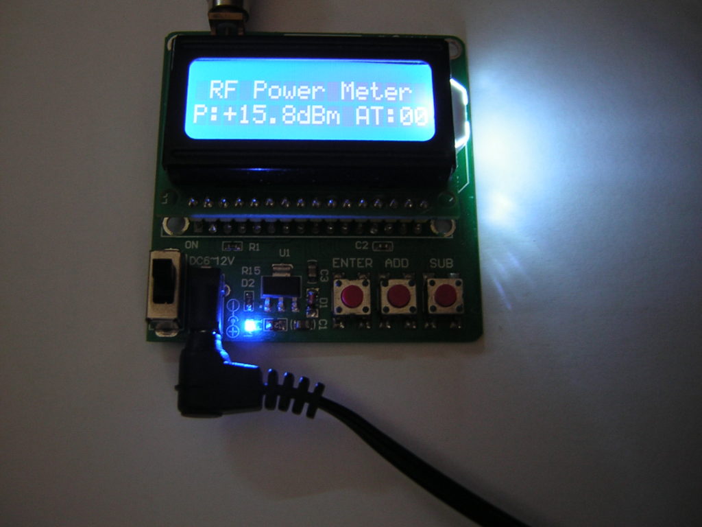
My power meter showed 15.8 dBm, which corresponds to about 38 mW.
So far, the results were very encouraging. Spots were reported from all over Europe.
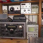
My New WSPR and FT8 Setup
During the Corona lockdown I had some time to reactivate my Ham-Radio station. I strung a wire of 20 meters length from the window of my shack under the roof to a telescopic fishing rod of 6 meters length in my garden. Then I wound an UnUn transformer on a ferrite core, to match the wire to the 50 Ohms output of my transmitter. I followed the instructions of Steve, G0KYA but changed the impedance ratio to 1:16 (3:12 winding ratio) which resulted in perfect match on the 40m and 20m bands. My explanation for this: Some of the antenna wire was inside my shack. This increased the capacitive load at the end of the wire and reduced the impedance at this point. On 40m and 20m the SWR is under 1.5 and there is no need to use the antenna tuner of my FT-900.
This FT-900 transceiver is 21 years old. Fortunately, it already had CAT-control. The output power was reduced to 1 Watt for WSPR and 5 Watts for FT8 operation. My power supply is a 28 Ah lead acid battery, because all the switch mode supplies that I tried were to noisy.
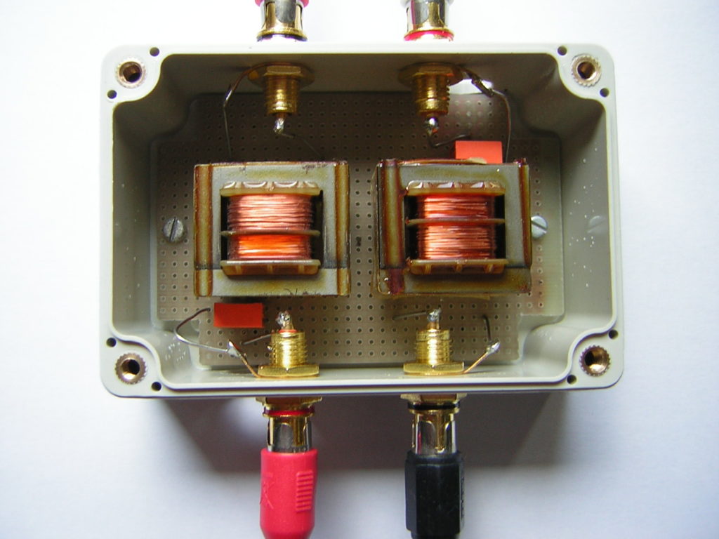
I purchased a USB to CAT cable from Steve, G8XGG which works perfectly well. For the audio connections from the TRX to the PC I made a transformer box, so that there were no ground loops. It also worked flawlessly.
My software is WSJT-X running on an old 32 bit laptop under UBUNTU-Linux.
My 30 dBm WSPR signal was already received in the USA and in Brazil. I’m very happy with that :-).
I was very surprised to find that there was much more activity on the bands in FT8 than in the traditional CW and SSB modes.
I have now replaced the laptop with a Fujitsu Thin Client S720, which was offered as a used device very cheaply (€20). It works without a screen or keyboard under Debian Linux and is controlled remotely via a VNC connection. Unfortunately there was now strong 100 Hz hum pickup on all bands. After some experiments I found out that this was obviously caused by the transformers in the audio lines between the transceiver and the thin client. That’s why I left out these transformers and made direct connections with simple audio cables. This almost completely eliminated the hum.
I also no longer use the UnUn transformer to match the antenna. I replaced it by a 200 Ohm dummy load.
Without an antenna connected, the SWR on the transceiver is now a maximum of 4:1. But, with the end-fed wire connected, it is now less than 2:1 on all bands. The built in tuner of the FT-900 can match that easily. The losses should not be higher than 3 dB. The WSPR reports achieved with 2 watts (33 dBm) are very satisfactory on all bands.
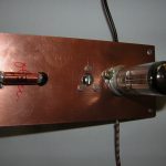
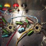
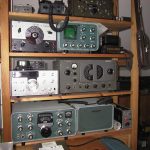
My Regenerative Receiver
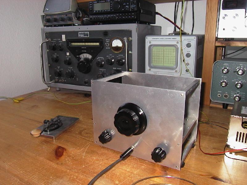
Here I want to show you my regenerative receiver:
It uses two 12AH7 double triode tubes. They just happened to be available in my junk box.
Here is the schematic: Regen.pdf
The first two triodes are connected in series, so that they act as a synthetic tetrode. This „cascode“ configuration was discussed in detail by David Newkirk on his excellent website.
The detector circuit presented here was originally used in a receiver that was lent to me by a fellow ham in 1968 when I just started my amateur radio career. It was a kit sold by a German company (Technik-Versand Bremen) and worked perfectly well in those days even on the 10 meter band. I always regretted having given it back so, I wanted to build a replica now. This works even better than the original.
Regeneration is controlled by adjusting the voltage of the second triode’s grid. When the regeneration control is at its minimum position, that means we have 0 Volts at pin 5, there is also no anode voltage at pin 3. The voltage at pin 6 is at its maximum then. When the regeneration control is engaged (voltage at pin 5 increases) the voltage at pin 3 also rises up. At the same time the voltage at pin 6 decreases, because the tube is drawing current and there is a drop across the 100k resistor.
The second 12AH7 works as a two stage audio amplifier. I tried to reduce the number of components to a minimum so, there is no cathode RC-combination in the audio stages. The necessary negative bias voltages are produced by the small grid currents flowing through the 10 MOhm grid resistors (grid leak bias). With my 10 MOhm VTVM I can measure about -0.65 Volts at the grids so, the actual voltage should be about -1.3 Volts. There is no noticeable distortion of the audio signal.
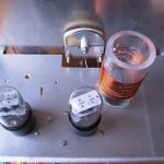
The coupling capacitors in front of the grids are quite small. This helps to reduce the hum. I tried an output transformer in an earlier version (you can still see the slots on the chassis where it was mounted). I hoped to get more audio output this way. But this was a disappointment. So, it was replaced with the original RC-combination (25k/.68µ) shown in the diagram with no ill effects. I can use high and low impedance headphones with good volume. The low impedance ones sound much more „bassy“.
The receiver is very sensitive compared to the pentode circuits I tried before. Using a two feet test lead as an antenna it hears everything on 40m that the R-388 does. Of course, the selectivity is not comparable. But in most cases this is no problem (the selectivity is between the ears of the operator ;-)). Regeneration control is very smooth without any noticeable frequency pulling or hysteresis. But, the regen needs a good ground. In my installation this is a connection to the heating pipe. My shack is located under the roof in the second floor. So, this ground connection is quite long and probably also acts as an antenna. Without this ground the receiver shows severe hand capacity effects and is difficult to tune.
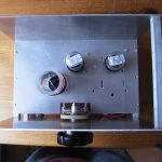
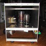
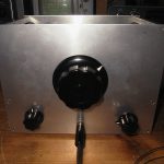
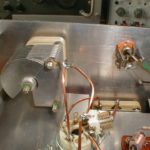
The big center knob drives the band-spread tuning cap. This cap is rather small. I had to remove most of the rotor plates to get a tuning range from 7.0 to 7.2 MHz. It rotates very smoothly and without using a reduction drive tuning in an SSB station is no problem at all. In the lower left you see the control for the band-set capacitor. The knob in the lower right drives the potentiometer for regeneration control.
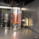
The plug-in coil is tailored for the 40 meter band where we find a lot of active CW stations here in Germany. It has 18 turns (about 9 µH) with the tap at 5 turns from ground. This tap position needs some more experimentation. I will try to lower the tap to 3 turns so that oscillation starts at a slightly higher voltage at pin 5 of the second triode.
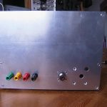
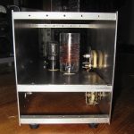
The power supply for my regen is mounted inside the box of a butchered PC supply. I ripped off everything and just kept the case, the AC input socket, the on-off switch and two 330µF electrolytic capacitors. The ‘ugly construction’ works flawlessly ;-). The B+ output delivers about 70 Volts. In spite of the simple circuit, this voltage is quite stable and clean because the receiver draws very little current (about 10mA). Rectification and stabilization of the heater voltage was applied to prevent any hum. The diode in the ground lead of the regulator raises the output voltage to exactly 12.6 volts. Later I added a bleeder resistor of 1 kOhm to the output which is not shown in the diagram.
Additional pictures:
Jones QRP TX
The components for this transmitter had been laying around in my scrap box for almost 40 years. Now I thought it was time to build it.

The first time I came across this circuit was in 1961 when I read the book “Funkfernsteuerung für den Modellbauer”. This was a translation by H. Bruss and Hans-A. Pfeil of the English title “Simple Radio-Control” by H. G. Hundleby. The circuit was called the “Aeromodeller Transmitter” and was a free running oscillator without a crystal. I found the adaption to crystal control in the German book “Drahtlose Fernsteuerung von Flugmodellen” (Radio Control of Model Aircraft) by Karl Schultheiss, DL1QK.
After looking at the circuit diagrams offered on the ‘Glowbugs’ server I realized that this actually was a Jones transmitter. But there was no reference made to the Jones circuit in the above mentioned publications.
See the circuit diagram here: jones.pdf
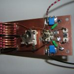
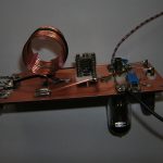
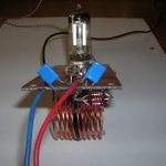
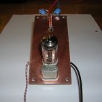
The transmitter is built on a piece of two sided copper-clad epoxy board. The bottom layer serves as a ground plane. Connections are soldered on islands (abt ½” squared) made of the same material glued to the surface. The coil has 12 turns of No. 16 copper wire. The diameter is abt 1″ and the length abt 1¼”. It was wound over a wooden dowel and fixed with three pieces of fiber glass rod (from a kite shop). The antenna coupling coil is one turn of insulated stranded wire wound over the center of the plate coil. The choke has 25µH.
For the first test I used the power supply of my regen. With only 70 volts on the plates the power input was quite low (only 350 mW). Stability was good but, it chirped heavily. The chirp was reduced when I tuned the plate circuit more to the high frequency side and not to the lowest dip.
At school I had the opportunity to connect the transmitter to a spectrum analyzer. When the plate circuit was tuned to the lowest dip, it produced a lot of harmonics. The odd harmonics were only 15 to 20 dB down from the fundamental and the even harmonics abt 30 to 40 dB. It was interesting to detune the plate circuit to the high frequency side until oscillation stopped, and then go back slowly to resonance. I stopped at the point where oscillation just started again (not yet at the lowest dip). Now the signal was very clean. You could only see the fundamental. The harmonics were in the noise!
This transmitter was built only for experimentation. Now I have gained enough experience to start a real project, a 40 meter Jones TX. It will use a 6Z7G tube (I like the symmetrical pin-out) and a rock I obtained from Bry, AF4K.
Additional pictures: