Home » 2020

Yearly Archives: 2020

Categories

Archives

My Model Flying History (1965)

1965: This year was very important for me. I designed and constructed two glider models. The first was quite a failure. It was built way too heavy and the wing had a constant chord, which was unfavorable. It didn’t fly very well and broke after only a few test flights. Unfortunately I don’t have any photos of this model. I received a lot of information from the experienced model pilots from Kaltenkirchen about the mistakes I had made with this model. Therefore, the next construction should be much better.

In the meantime, my friend Joachim Jürgensen had designed and built his own model. The special thing about it was that the wings were very much tapered. The root chord was 200mm and the chord of the tip was only 100mm. This model had a very good glide angle as long as it was flying straight ahead. As soon as you tried to make a turn, the inner wing tip stalled and the model began to spin. It was almost impossible to fly.

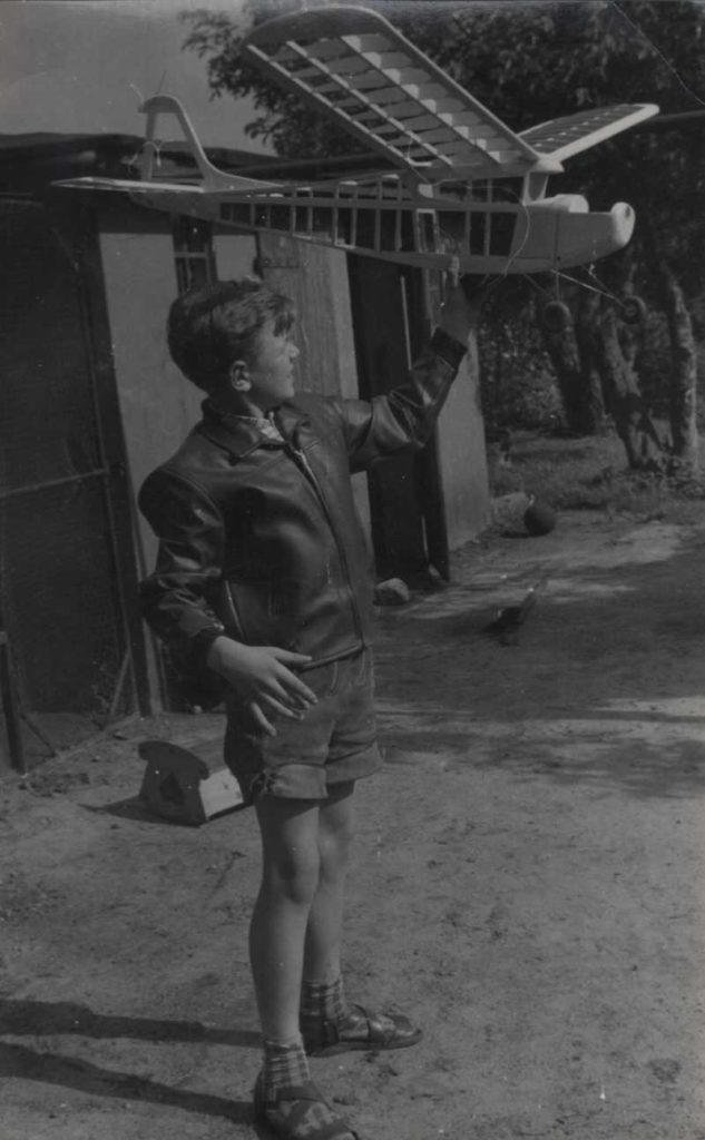
So it was clear to me that I had to find a better compromise here. My new wings got a root chord of 200mm and a tip chord of 150mm. In addition, over the last third of the half span the wing got a washout of about 2 degrees, in order to prevent the tip stall.

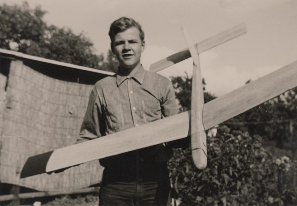
The picture shows me, holding the model. I published more information and more photos in another post.

My father had built another sailplane of his own design:

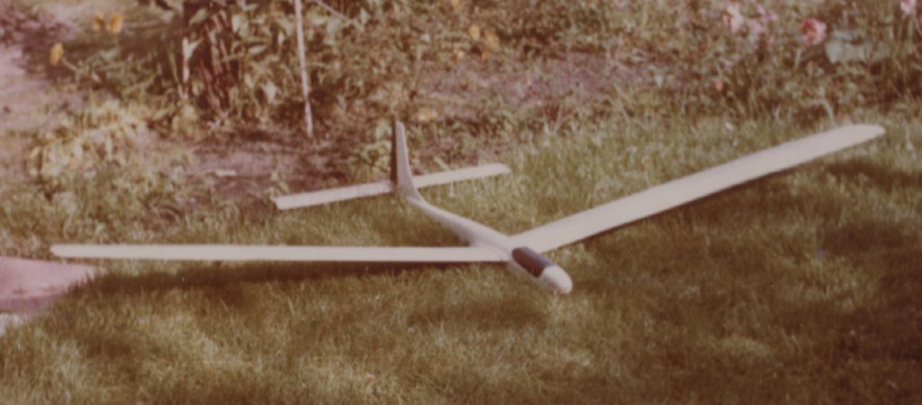
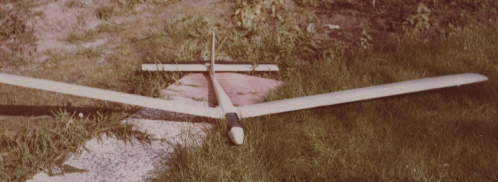
It was a bigger than mine (2500mm wingspan) and already had rudder and elevator control. We had built a new radio from kits offered by the “Reuter” company.

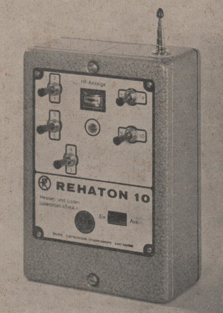
The picture shows the fully equipped 10-channel version of the transmitter. Ours only had 4 channels (two sticks).


My Model Flying History (1964)

1964: I don’t have many memories of that year. I also couldn’t find any photographs. I started playing guitar in 1962. More about that is in another post. So I guess I spent most of my time on it. I also did something with electronics. It was mainly about circuits for remote control, but also about detector-receivers for radio reception. We certainly went to Kaltenkirchen a lot to fly our glider models there.


My Model Flying History (1963)

1963: In the meantime, our interest in a powered radio-controlled model grew again. In the “Modell” magazine we saw the picture of the “Tele-Pilot”. It was a design of Heinz Siegle and offered by the “Engel-Modellbau” company (it no longer exists today). At the Vietzke model shop we found the “Engel”-catalog and we ordered the kit. Here is the page of a later catalog. The price was not too high. It was a bigger model with a 65 inch wingspan and a large dihedral. We were convinced that this model had to fly well. In our opinion this big plane needed a big engine. So, an OS-Max 29 with 5cc displacement was ordered.

Since our garage was now occupied by our car, it could no longer be used as our workshop. Fortunately we were able to free a corner in our cellar room and install a workbench there. When the kit arrived, we started the assembly in our new cellar workshop. It went together without any problems. The following picture shows the completed uncovered frame without radio and engine installed:

The next picture shows me presenting the frame in front of our chicken house:

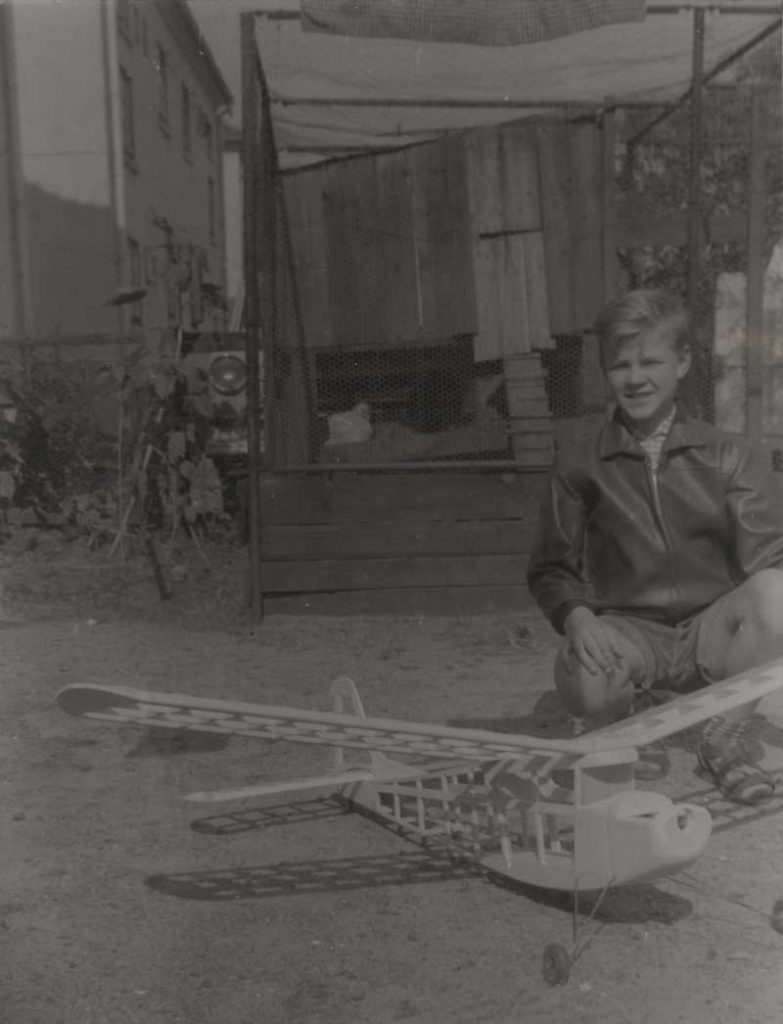
The frame presented by me (wearing the famous Lederhosen) in the backyard of our house:

It was an impressive model for sure.

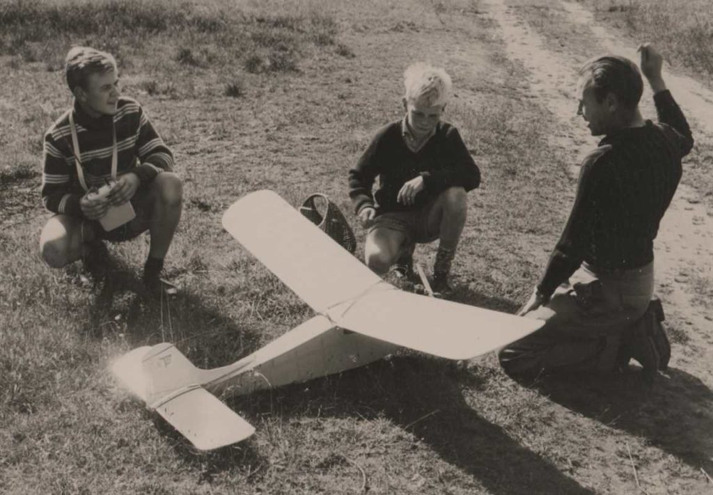
A few weeks later we proudly carried the model to our local grassland “airfield”. Of course there were some curious spectators again. We made some initial hand starts without the engine running. The model glided smoothly like a sailplane. The center of gravity and the longitudinal dihedral angle were obviously correct. We dared to try the first powered flight. The engine was started without any problems. We tested the radio (Metz-Mecatron) and it worked flawlessly. The engine could be throttled by the third channel of our radio. Push the button: engine idling. Push the button again: full speed. The next picture shows the model just prior to the first flight. I hold the transmitter, my father gives commands and the son of our neighbors, Holger Tamm, assists us.

I took over the transmitter, my father threw the model in the air. It went up straight, beautifully and evenly. It responded to the rudder instantly and so I let it make a big left turn. In very short time the model reached a height of about 100 meters. What a beautiful sight. When I thought that it was high enough I pushed the button for low engine throttle. That worked well and the engine slowed down. But even in this throttled down position, it still had so much power that our model continued to climb. Obviously we had too much engine power. Our OS-Max 15 would probably have been sufficient. But how should I get the model down now? We couldn’t let the model climb until it was finally out of sight.

The tank was still rather full and we had no elevator control. I got the idea that a spiral dive would be the right method to get the model down. So I gave full left rudder. The spiral began and the model quickly lost height. I put the rudder back on neutral to end the spiral but the model didn’t want to recover. It did not even react on full right rudder. The spiral continued. Eventually the model disappeared behind a house and could not be seen any more. We didn’t hear the crash but it was clear: the model hit the ground somewhere. Great horror! We quickly ran in the direction where we suspected the impact would be. Behind a couple of houses we eventually found the debris in a ditch between a front yard and the street.

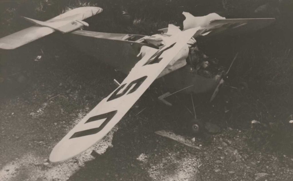
In our opinion this was beyond any repair. With the experience I have today I would have repaired it. Despite the total loss, we were still rather lucky. The model could have hit the roof of a house or injured or killed a person.

In retrospect, it was also clear to me that our “airfield” in Elmshorn would have been too small anyway for an orderly landing approach. We decided to make our next attempts only in Kaltenkirchen.


My Model Flying History (1962)

1962: My father had finally made a driver’s license for a car. Our first car was a used Volkswagen Van that was missing the middle bench. Now we could drive to the Kaltenkirchen Moorkaten airfield more often on weekends. This airfield originally was a military training area. But the local club FAG (Flugtechnische Arbeitsgemeinschaft Kaltenkirchen) was allowed to use it over the weekends. There we could see for the first time how radio-controlled models were properly flown. In addition to some powered models of the RC1 class (today F3A), there were mainly sailplanes of the RC4 class (today F3B). The models were started up with a 200m long nylon cord by a runner using a pulley. A rubber high-start was not common at that time because it was not allowed for competitions. And the members of that club were very active competition flyers.

In a kiosk in Elmshorn I discovered the “Mechanikus” magazine. It not only contained very interesting articles on the design and construction of model aircraft but also on model ships and model railways. From now on I bought and read every issue of this monthly magazine. Werner Thies, in particular, has to be mentioned here as an author who described his glider models in detail. And he also was the chairman of FAG Kaltenkirchen. I learned a lot from him.

Very soon our decision was made: our radio control units had to be installed into a glider. Of course we didn’t want to buy a kit. We were brave enough to design it ourselves. It had to be a little bigger than the “Geier” because of the weight of the radio control. The fuselage should look elegant, so a simple box construction was not an option. Since we couldn’t afford a fiberglass fuselage, we built an oval one from balsa wood. The wings got a span of 2.50 meters (nearly 100″) and were fastened with tongues and boxes, as we knew it from the “Geier”. The sizes of the horizontal and vertical stabilizers were calculated according to the instructions by Werner Thies. Our radio only allowed rudder control. We didn’t think about spoilers yet.

Some weeks later we went to Kaltenkirchen with the finished model. A few other modelers were already there and eyed up our plane when we took it out of the car and assembled it. At first we tried some hand launches. Helmut Noffz, one of the experienced model pilots, watched us with interest and finally said: “The balance point is not correct!” He balanced the model with his fingers under the wings and found that the center of gravity was to far back. We had determined it according to our experience with the free-flight models “Donald Duck” and “Geier” and that was not right for a radio controlled glider. Mr. Noffz showed us where the balance point should be and that was in the first third of the wing chord. He had a few pieces of lead in his toolbox. We cut a slot in the model’s nose block with a knife and temporarily stuck the lead pieces inside. Now the hand launches looked a lot better and the model glided beautifully. Eventually, also the position of the tow hook had to be corrected. After that, we dared to make a first high start, which went without any problems. The model climbed straight up and was released at a height of more than 100 meters. It was very easily controlled and flew more than two minutes. The landing was not very close to us, but the model remained intact. What a sense of achievement! We drove home thoroughly happy.

I had been interested in control line flying the whole time. So we looked for a model kit that should be appropriate for the Hurrican engine. We decided on the “Ultra-Stunter” from Graupner. My dad assembled it because the fuselage had an oval cross section and therefore was a little difficult for me to build. Of course we had to buy a lot of additional accessories again. The most important one was a tethered flight grip “Meister” from Graupner which already included the wires. The finished model should be tried out on our small grassfield near our home. We were watched by a number of curious onlookers. The lines were laid out and the engine started. I should do the first flight. My father released the model. It immediately took off and went into a loop. I was so surprised that I couldn’t react fast enough. Before I could give down elevator, the model was already descending. The loop merged into a figure nine, which ended with full speed in the ground. Everything was totally destroyed and hardly repairable. We were utterly ashamed and disappointed. The Ultra-Stunter was an aerobatic model with extremely effective control surfaces. It was therefore completely unsuitable for beginners. We should have studied the description in the Graupner catalog more carefully.

A few months later I built a new control line model together with my friend Joachim Jürgensen. When designing it, we made sure that it was easy to fly for a beginner. I found instructions for this in the book “Fesselflug-Fibel” written by Gernot Nobiling. If only I had read this book beforehand! This new model flew without any problems and was easy to control. We had a lot of fun with it.


My Model Flying History (1961)

1961: So far I had assembled my models on the kitchen table. In the meantime we had cleared our corrugated iron garage so that we could use it as a workshop. We didn’t have a car back then. The next project was the free flight model “Donald Duck” of class A1 from Graupner. Unfortunately, we had made a mistake during construction: The trailing edge strip of the wing was not raised at the front but laid flat on the building board (as we knew it from the “Little UHU”). Therefore, the airfoil was incorrect and the flight performance was correspondingly poor. The model already had curve control and a thermal brake. We coped well with that and made a lot of flights. A fuse was used to trigger the thermal brake.

Next, a larger free-flight model was needed. It was a “Geier” of class A2 (now F1A) published by the Robbe company. It promised to be a competitive contest model. There was no kit available, just a blueprint. So we built everything completely from raw material. The model had a two piece wing and we got to know a tongue and box attachment. This time the airfoil was built correctly and the flight performance was impressive. We gained a lot of experience with this model.

One day, while browsing the Vietzke model shop, I discovered the book “Funkfernsteuerung fuer den Modellbauer”. It was a translation by H. Bruss and Hans-A. Pfeil of the English title “Simple Radio-Control” by H. G. Hundleby. I absolutely had to read that. I literally soaked up the content and that was my first contact with radio technology. I still have this book and I still like to look inside. It’s very tattered now.

From time to time we went to Hamburg, the next big city, for shopping. On one of these occasions we also visited the large model making department of “Spielzeug Rasch”. That was of course not to be compared with the small shop in Elmshorn. Our eyes widened more and more when we saw the many model kits and radio control sets that were on display. However, everything was so expensive that we couldn’t afford it. After all, we bought a few copies of the “Modell” magazine that we found there. I read all of them from cover to cover and was thrilled by all the new information. I was able to persuade my parents to subscribe to this magazine.

At the end of the summer we visited a model air show at the Hartenholm airfield near Bad Segeberg. What impressed me most was a biplane called “Captain”, which was flown by radio control. The model performed wild capers in the sky and hardly ever flew straight. It only had a 1-channel system with a rubber powered escapement. Today I know that the pilot probably had problems calming the model down with the right commands. Only when the engine finally stopped the flight became straight and the landing succeeded rather smoothly.

Some model shops exhibited their products along the site. One of them was the Carl Leonhardt company from Bad Segeberg. I was particularly interested in the new 3-channel radio control system produced by Metz. It seemed to be comparable to the Graupner “Bellaphon” system that we knew from the magazines, but was much cheaper. We took some handouts and leaflets with us, to study them thoroughly at home. I still have them.

My father had worked overtime and saved some money. We therefore decided to order the Metz 3-channel system at the Vietzke model shop. After a few weeks it actually arrived and we were able to pick it up. Of course, it had to be officially registered with the Federal Post Office and a fee of 10 DM had to be payed every year. I still have the certificate.

Now of course we needed a new model for it. Although it would have been more sensible to build another glider, it now had to be a model with an internal combustion engine. The “Satellite” model was particularly recommended for this purpose in the Graupner catalog. This was a replica of the American model “Live Wire” by Harold De Bolt. But the kit was very expensive. You could get the new “Piper Tri Pacer” for much less money, and it looked even nicer. So we decided on this model. We later realized that this was a mistake.

My father built the model almost alone because it was to complicated for me. Of course, only the “Taifun Hurrican” Diesel engine was considered as the drive. It had to be broken in first. Back then, you could run an engine in the garden without a silencer without being scolded by your neighbors. During the working days, my father took the compression lever with him so that his son would not be able to run the engine while he was away. He knew me!

Eventually, the “Piper” was ready to go and we made our first attempts on the grassfield near Wittenberger Strasse. However, we found that the “Piper” did not want to roll properly in the tall grass to gain enough speed for takeoff. We had, of course, attached the beautiful wheel pants. So we found a tarmaced field path nearby for our next trials. But the model always only rolled a few meters, broke out to the side and stuck in the high grass aside of the road. It didn’t want to take off.

We came to the conclusion that the engine was to weak. So we needed a bigger one. This time it should be a glow plug engine. The OS-MAX 15. Of course, new accessories were needed. A glow plug clamp, a starter battery and a different fuel. After breaking in, the engine was installed in the “Piper”. But the following attempts to start were just as unsuccessful as before. The model didn’t want to take off. We could have tried to start the model directly from our hands but didn’t dare to do this.

Out of desperation, we contacted my father’s colleague Gerd Mix again and met him in Kollmar at the Elbe. He was a very experienced model pilot and took a close look at our “Piper”. He found no serious flaws and thought the model should definitely fly. We should try to start it directly from our hands . Together we went to the beach and started the engine. Gerd Mix took the model and threw it firmly into the wind. The model stalled immediately, turned on her back and crashed into the ground. Almost everything was broken and looked beyond repair. We never found the reason for this failure. For us this was the end of the “Piper” experiment.


My Model Flying History (1960)

1960: In a Mickey Mouse issue I found the instructions for building a chuck glider including a blueprint of the plan and all the information for the  material required. When I showed the plan to my father, he didn’t really believe that I would be able to build the plane. However, he agreed with my mother that we should buy the material. There was a small model shop close to the harbor of Elmshorn. It was operated by a couple named Vietzke. He was a passionate hunter and mainly sold rifles. His wife took care of the model making department.

To our horror, we found that balsa wood was only sold in whole sheets measuring 100 by 10 cm. We had to buy three sheets in three different thicknesses. Plus a tube of UHU-Hart. All together, that made around 5 DM. A lot of money for us in those days! When my father came home in the evening he said: “Well, then start building! If it actually flies, I will buy you a larger model.” Of course that was a huge incentive for me.

I assembled the model according to the plan. But since I had no practice in gluing the parts together exactly, the end product looked rather crooked. Nevertheless, I made my first flight attempts in our garden and in the “Zeppelinplatz” grassland. The model never flew straight but made loops and rolls depending on how hard it was thrown. I thought that was okay and was thrilled.

Fortunately, I was able to transfer my enthusiasm to my parents. So, a few weeks later, we went back to the model shop and had a look at the kits that were available. Fortunately, Mrs. Vietzke advised us very well and recommended a small free flight model, called “Little UHU” from Graupner. We also bought the necessary accessories: trim lead, pore filler, dope, towline. The tissue paper was already included with the kit.

I assembled the model with the help of my father. Since my father was a painter by profession, the tissue covering and painting job was no problem and the result looked really nice. We needed a larger grassfield for the test flights. We found it between Weidenstrasse, Waldweg and Wittenberger Strasse. Today this field is also completely covered with single-family houses. Back then there was a lot of space and you could climb up the dam of Wittenberger Strasse to start the model from an elevated position. We did not use the full line length for the high start, but limited it to approx. 30 meters. The “UHU” had no automatic steering and always flew straight ahead. It had to be recovered from an adjacent hedge almost each time. In any case, we had a lot of fun and were very motivated to continue.


My Model Flying History (1959)

1959: Our family had moved to a new location in Elmshorn. The name of the street was Langenmoor. I glued together some plastic kits for small fighter planes (ME-109 etc.) produced by the Revell company. I could only let them fly in my imagination adding the engine noise with my mouth.

I also built kites out of hemp twine, paper and pine strips. A carpenter in Goethestrasse sawed these strips for little money. I was able to fly the kites on a grassland between Langenmoor and Danziger Straße. That was a lot of fun. Today, this field is completely covered with apartment buildings and is now called Zeppelinplatz.


WSPR with Raspberry Pi

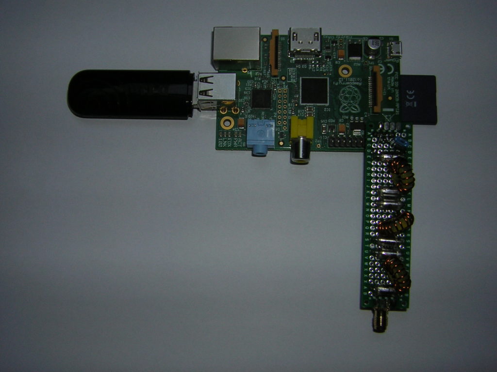
After my successful experiments with WSPR and FT8 on my FT-900, I wanted to try a low power stand alone beacon for WSPR. I happened to find an old Raspberry Pi in one of my bottomless drawers.

A search on the WEB revealed that there was a way to convert this board into a transmitter. Very inspiring instruction was found on a German website. The program called WsprryPi was downloaded from GitHub. The instructions for installation and usage on this site were very detailed and helpful.

I wanted to run the beacon autonomously without connecting another controlling PC. DL7VDX suggested to write a script which was started automatically on boot-up. I tried this, but had no real success. The easiest way was to add a command line to the /etc/rc.local file. This worked perfectly well.

The Raspi was connected to my local WLAN via a USB-stick, to receive a time signal from an NTP-server.

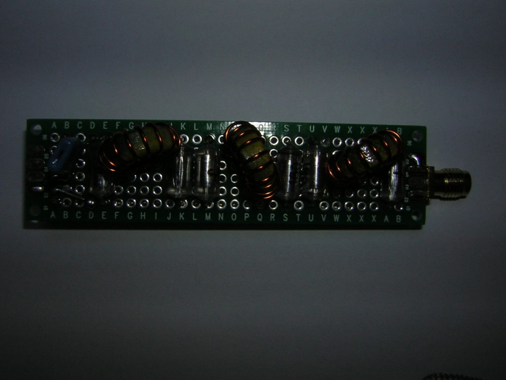
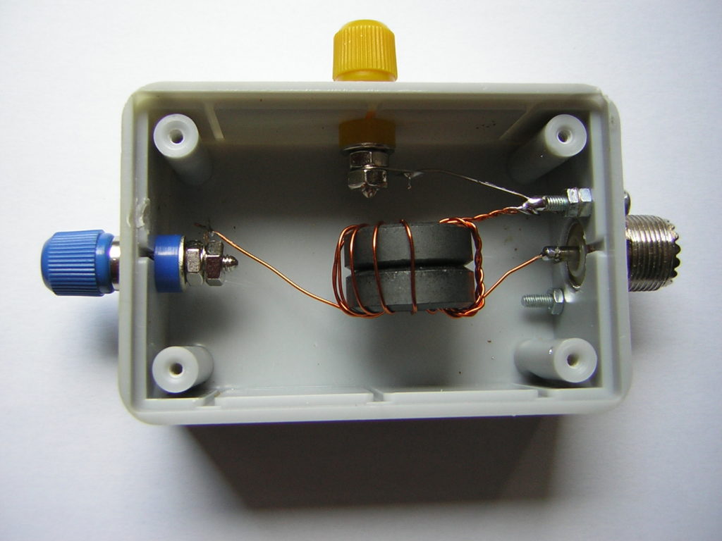
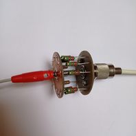
Very important: A low-pass filter had to be inserted between the output of the Pi and the antenna!  I found detailed instruction for this on the QRP-Labs website. Fortunately, I had some AMIDON T-50-6 cores laying around. Three coils were wound with 0.6 mm magnet wire (~AWG 23). All the components were soldered to an experimental circuit board:

One problem was, to measure the filter’s frequency response. The only test equipment I had for this was my FA-VA5 antenna analyzer.  I inserted the filter between this instrument and a 50-Ohm dummy load:

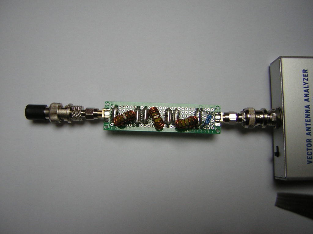
Then I scanned the Z-response . . .

. . . and SWR over frequency:

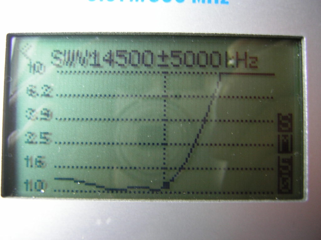
So, in my opinion, the quality of the filter was adequate.

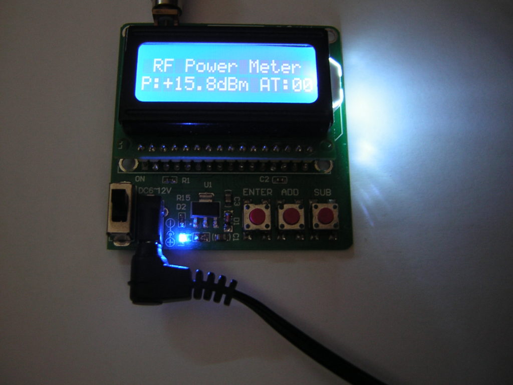
My power meter showed 15.8 dBm, which corresponds to about 38 mW.

So far, the results were very encouraging. Spots were reported from all over Europe.


My New WSPR and FT8 Setup

During the Corona lockdown I had some time to reactivate my Ham-Radio station. I strung a wire of 20 meters length from the window of my shack under the roof to a telescopic fishing rod of 6 meters length in my garden. Then I wound an UnUn transformer on a ferrite core, to match the wire to the 50 Ohms output of my transmitter. I followed the instructions of Steve, G0KYA but changed the impedance ratio to 1:16 (3:12 winding ratio)  which resulted in perfect match on the 40m and 20m bands. My explanation for this: Some of the antenna wire was inside my shack. This increased the capacitive load at the end of the wire and reduced the impedance at this point. On 40m and 20m the SWR is under 1.5 and there is no need to use the antenna tuner of my FT-900.

UnUn

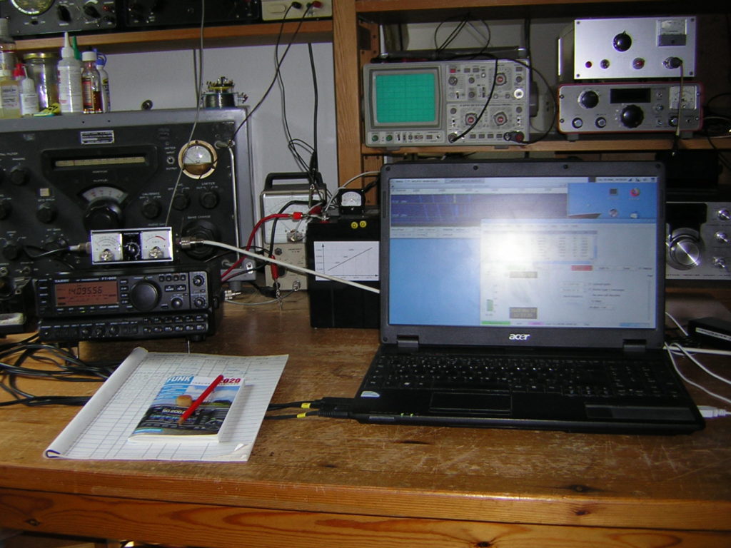
This FT-900 transceiver is 21 years old. Fortunately, it already had CAT-control. The output power was reduced to 1 Watt for WSPR and 5 Watts for FT8 operation. My power supply is a 28 Ah lead acid battery, because all the switch mode supplies that I tried were to noisy.

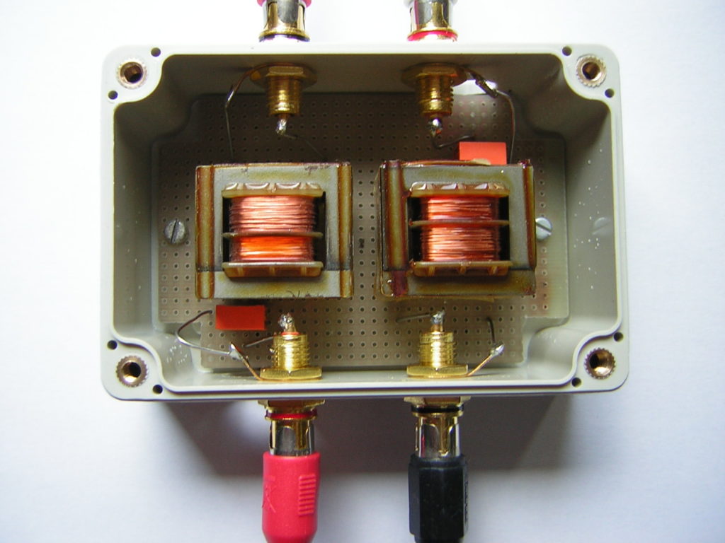
I purchased a USB to CAT cable from Steve, G8XGG which works perfectly well. For the audio connections from the TRX to the PC I made a transformer box, so that there were no ground loops. It also worked flawlessly.

My software is WSJT-X running on an old 32 bit laptop under UBUNTU-Linux.

My 30 dBm WSPR signal was already received in the USA and in Brazil. I’m very happy with that :-).

I was very surprised to find that there was much more activity on the bands in FT8 than in the traditional CW and SSB modes.

I have now replaced the laptop with a Fujitsu Thin Client S720, which was offered as a used device very cheaply (€20). It works without a screen or keyboard under Debian Linux and is controlled remotely via a VNC connection. Unfortunately there was now strong 100 Hz hum pickup on all bands. After some experiments I found out that this was obviously caused by the transformers in the audio lines between the transceiver and the thin client. That’s why I left out these transformers and made direct connections with simple audio cables. This almost completely eliminated the hum.

I also no longer use the UnUn transformer to match the antenna. I replaced it by a 200 Ohm dummy load.

Without an antenna connected, the SWR on the transceiver is now a maximum of 4:1. But, with the end-fed wire connected, it is now less than 2:1 on all bands. The built in tuner of the FT-900 can match that easily. The losses should not be higher than 3 dB. The WSPR reports achieved with 2 watts (33 dBm) are very satisfactory on all bands.