Home » 2017
Yearly Archives: 2017
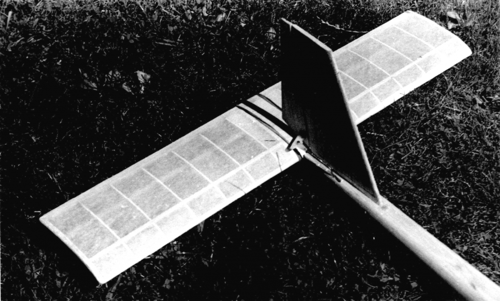
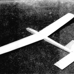
My Riser V-Tail
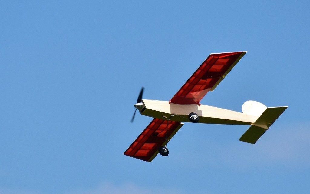
Here I want to show you my version of the SIG-Riser model sailplane.
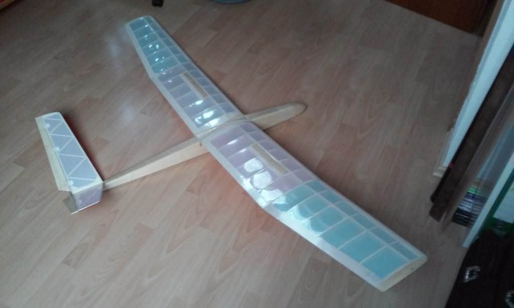
This year, the idea came up in our club, to organize a competition of the R.E.S. class. R.E.S. stands for “Rudder Elevator Spoiler”. This class for simple 2-meter model sailplanes has become extremely popular in Germany. As I wanted to participate in this contest, I had to build an appropriate model. My choice was the “Riser” offered by the SIG company. One reasson for this was the extremely low price for the kit.
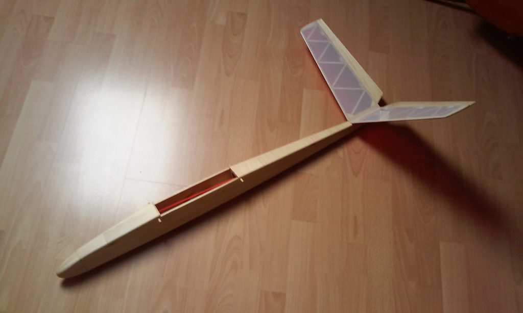
The building instruction was straight foreward, so I put the plane together in very short time. When it was time to build the vertical and horizontal stabilizers, I decided to make a change. I was convinced that the normal cross tail would be to heavy. So I changed it to a V-tail. I set the opening angle between the two sides to 120 degrees and extended their length by 15 percent to get enough area in the vertical projection. I hoped that nevertheless enough controllability was given. The maiden flight should show it.
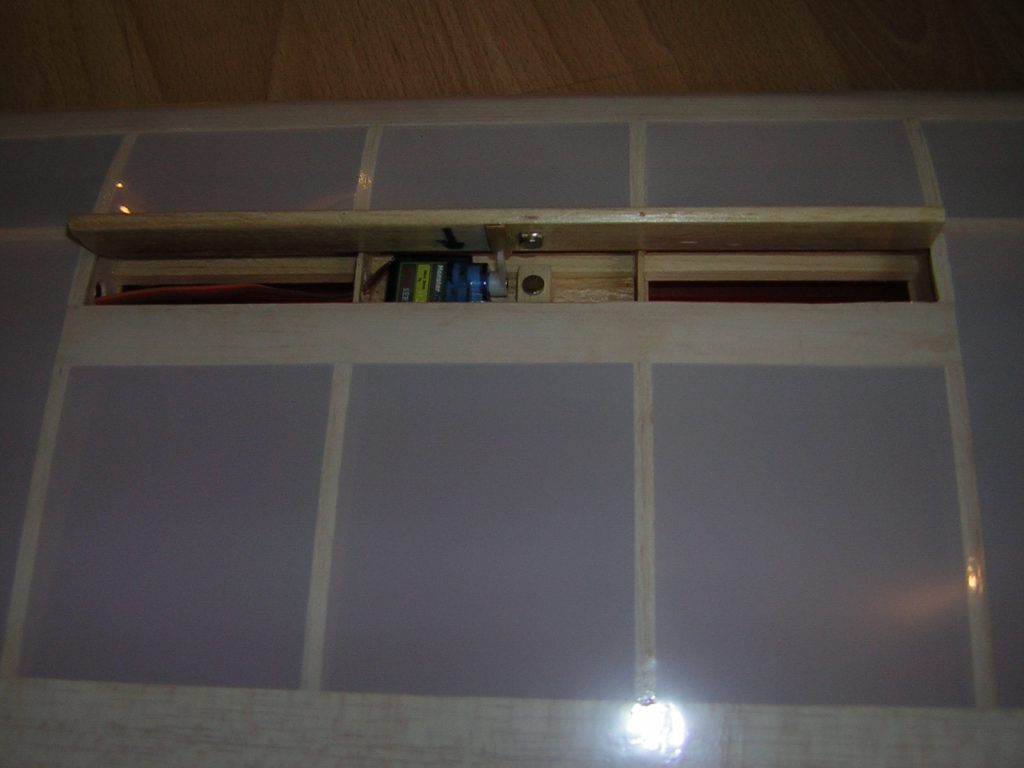
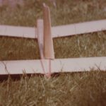
The plans for the model included an extra sheet for the installation of spoilers. Unfortunately, the material for this was not included in the kit. As I wanted to use two separate servos for the two wing sides, I had to think about a different way how to control the spoilers. Now they are hinged at the front edge with plastic tape and pushed up directly by the servo horns. Small magnets hold them down in the retracted position.
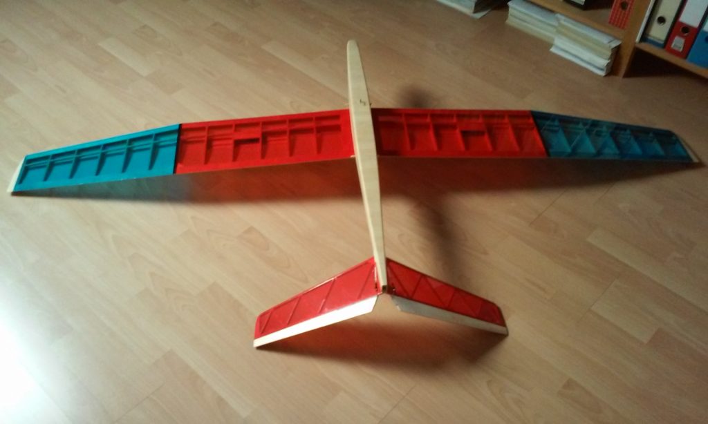
I covered the wing and the tail feathers with transparent OraLight. White on the top and red and blue on the bottom. The fuselage was just painted with clear lacquer. Despite of the lighter tail, a lot of ballast was still needed in the nose of the model to put the center of gravity in the right position. I decided to use a 2-cell LiPo of 2000 mAh combined with a UBEC-device. Now, the total flight weight came out at 630 g (~22 oz). So, this model seems to be more suitable for stronger winds.
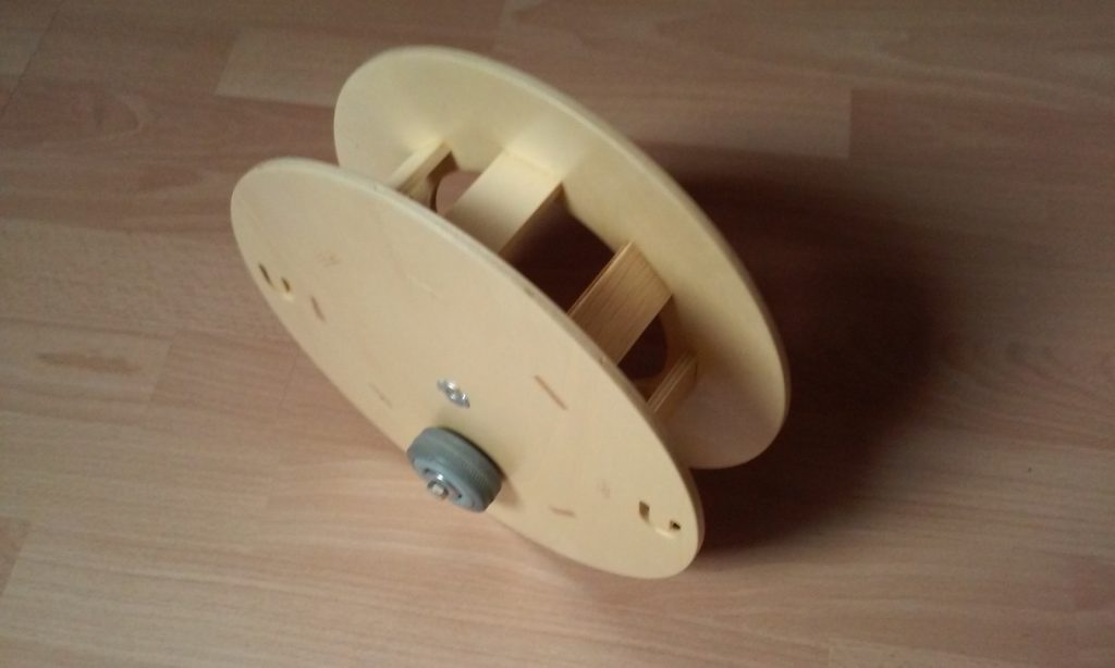
For the high start a special rubber is required, which is extended with a fishing line. For this I made a wooden drum from a kit which was provided by Modellbau Claus Thiele.
Varioprop Conversion
Here I want to show you, how I converted an old Graupner Varioprop transmitter to 2.4 GHz.
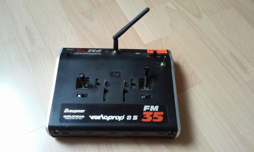
I didn’t want to have another transmitter with all kinds of bells and whistles. My intention was, to make an old transmitter usable again that was laying around in my cupboard. I have other radios that can do everything. On the other hand, I wanted to improve my programming skills for the Arduino microcontrollers.
As I wanted to use this transmitter especially for my new SFC-Stick, I limited the number of controls to four (throttle, rudder, elevator, ailerons). The two extra potentiometers in the center were not yet connected to the controller and the 3-position switch was not used in the program.
First, I removed all the electronic components, the antenna socket and the battery until only the mechanical parts (sticks) remained. Then an RF Module from FrSky (V8HT) was inserted. The new antenna socket was glued in with epoxy. Also, a new charging socket and a new on-off-switch were necessary. The battery is a 2-cell LiPo of 800 mAh which is absolutely sufficient. The transmitter now has a very low weight (670g ~23.6 oz).
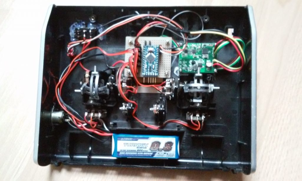
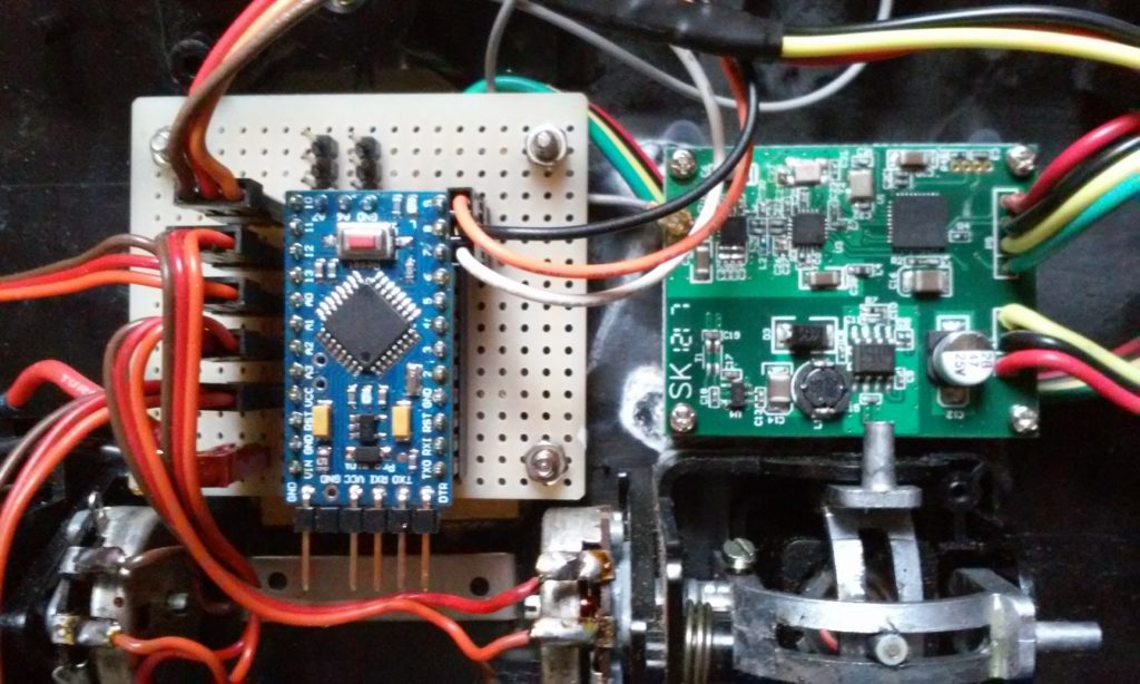
The PPM signal is provided by an Arduino Pro Mini.
You can find my sketch here: rc_encoder_sfc_stick
There is no display or keypad in the transmitter. If I want to change the program, I have to connect the Arduino to my PC and upload a modified sketch.
I use this transmitter specifically for my SFC-Stick model, which I have presented in another post.
My SFC-Stick
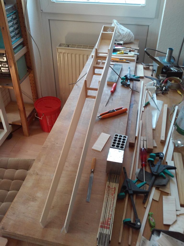
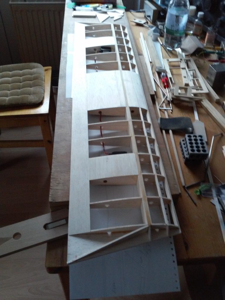
Here I want to show you my version of the Ugly Stick (SFC stands for Sport Flying Club). It was designed by a fellow club member more than twenty years ago as a project for our youth group. He provided some drawings the wing ribs and fuselage frames as milled parts and a stack of balsa wood for the remaining components. At that time, I obtained such a stack of material but never found the time to build the model.
Last year a new competition was devised in our club. We called it the “Fun Cup”. The rules: Within four minutes, as many rounds as possible had to be flown around two turnstiles 40 meters (~131′) apart. Within each round a “touch and go” had to be done in a landing field of 10 meters (~33′) in length. You got additional points for the final landing.
I really wanted to take part in this competition. But until that time, I had only flown gliders and did not have a single model with landing gear. What could I do? In February this year I discovered the material for the Stick in my cellar and started building immediately.
Originally, the wingspan should be 140 cm (~55″), but I decided to reduce it to 112 cm (~44″). The total length of the fuselage is also 112 cm. The wing was covered with transparent OraLight, white on the top and red on the bottom. The fuselage and the tail feathers were just painted with clear lacquer. The model is powered by an electric motor (DYMOND GTX-3546 (910kV)) and a LiPo battery (3s1p, 3300 mAh). The prop size is 11×7. The total flying weight is 1400 g (~50 oz).
The model flew very well. Since I had little time to train the “touch and go” part, my participation in the competition was not so successful. But most importantly, the model is still intact!
The following picture shows me holding the model after the end of the competition.
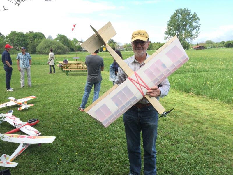
The model is controlled by an old Varioprop transmitter that I converted to 2.4 GHz.
How My Guitar Playing Started
On my 12th birthday my uncle gave me a guitar. It was an Archtop made by Framus. Sorry, but I don’t have it any more.
My parents payed for the weekly guitar lessons. My teacher was Mr. Thomsen in Elmshorn, Germany. This lasted until I was 16 years old. At that time I was pretty good in accompanying swing and dance music.
When I started my apprenticeship in electro mechanics, I put away the instrument and stopped playing. I became more interested in Model Flying and Ham Radio.
Between 1970 and 1974 I was a Radio Operator (Sparks) on various reefer ships, like the “Pica” of the “Laeisz” company:

On the long and lonely trips I missed my guitar. On one of our stops in Bordeaux, France, I took the opportunity to buy a classical instrument. It was nice to play again and it made my life on board easier. When I left the ship in Rotterdam, it was no problem to bring the guitar home.
After my holidays I had to enter the next ship in Los Angeles. Since I did not want to carry so much luggage, I left the guitar at home. Our first trip was to Tokyo, Japan. I only had a half day off to do some shopping. When I walked past a music shop, I saw an infinite number of guitars hanging on the wall. I could not resist and bought one of them, a Yamaha G-150A.
During one of my journeys my parents had to move and wanted to get rid of all “unnecessary” things. So they sold the Archtop and the guitar from Bordeaux.
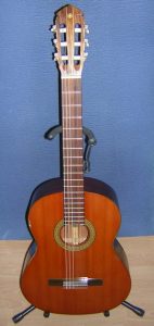
How I Rediscovered My Guitar
After many decades, in 2008, I rediscovered my Yamaha. It had spent its life in its gig bag covered with dust and had been pushed around from one corner to another. Despite the poor treatment she was in relatively good condition. The D-string was broken and there was a small dent in the front binding. After cleaning it and putting new strings on, I tried to play it again. The sound was pretty good and I could still remember some of the chords. But my playing had become very bad.
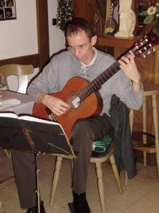
In the summer of 2008 I attended a classical guitar concert of Heinrich Wittrock in Darmstadt. I really loved his music. At the end of the concert I gathered all my courage and spoke to him. He was very friendly and I asked him if he knew someone who could give me some lessons. I was very surprised when he offered me to do it. We agreed on a date and started our weekly guitar lessons. He showed me everything; that is, he gave me a complete classical guitar training. Now I really learned to understand sheet music. The picture shows Heinrich playing on my 60th birthday party.
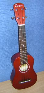
New Instruments
When I spent the first week of 2010 in Norddeich/Norden (East Frisia), I missed my guitar. So I bought a Ukulele in a music shop in Norden. It is a cheap instrument and the sound is a little dull, but playing it is a lot of fun.
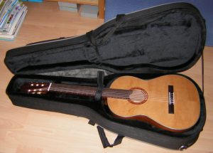
My last acquisition is a new classical guitar. It is a Hanika 50MC. I bought it in the Musikladen Eberstadt. It is a wonderful instrument and a real improvement over my Yamaha.
My Chuck Gliders
At the age of ten I found the plan for a small chuck glider in a Mickey Mouse magazine. I asked my mother if she would buy me the necessary balsa wood. She did and my father promised to buy me a kit for a larger model, if I managed to finish the chuckie and bring it to fly. He did not seem very convinced.
The instructions in the magazine were quite detailed and although I did not build the plane very well, it eventually flew.
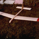
The model shown in the picture is a new one that was built when I led the youth group of the club. Wingspan: 380mm (15″), weight: 43g (1½ oz).
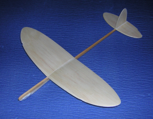
The next glider is a little bigger but lighter. Wingspan: 475mm (18¾”) weight: 36g (1¼ oz). It was made as a study model for a bigger RC version that I want to build.
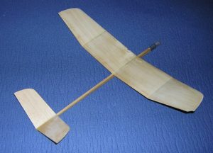
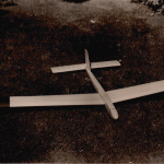
Also as a study model for a bigger RC version I built a tailless chuckie. Wingspan: 500mm (20″), weight: 21g (¾ oz).
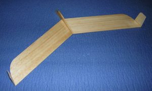
All of my chuckies are a little damaged from the test flights in my garden.
My School Project
In the last year of my junior high school I had to prepare a final year project. The subject was free. So I decided to build an RC sailplane and write about it. At that time, at the age of 15, I had only built models from kits. But now I wanted to design this one on my own. As I had read a lot of articles written by Werner Thies and Karl-Heinz Denzin in the German “Mechanikus” and “modell” magazines, I had pretty clear ideas about the size and the shape of the model. The picture shows me holding the finished product.
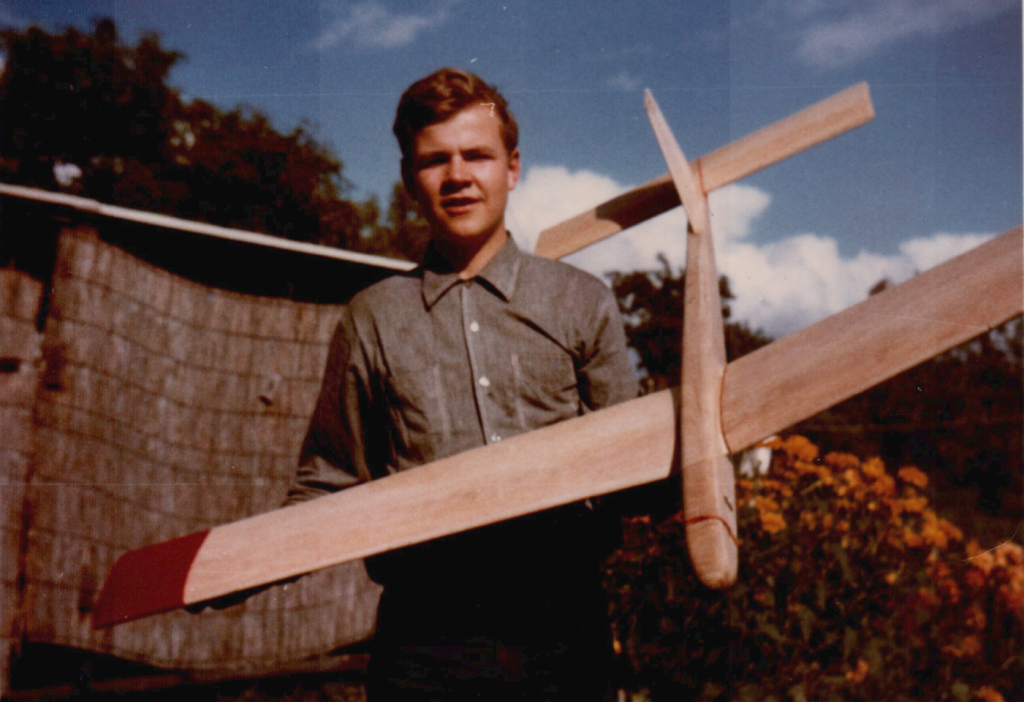
I’m sorry that I can’t show a drawing of this plane, but it was lost. Also the model doesn’t exist any more. So I can only describe it from memory:
Wingspan: 1800mm (~71″)
Root chord: 200mm (~8″)
Tip chord: 150mm (~6″)
Wing section: Goettingen 613
Stab section: Flat bottom, 10% thickness
Stab area: 25% of wing area
Weight: 1200g (~42oz)
The fully sheeted wings were fixed to the fuselage with tongue and box. The elevator was initially covered with tissue.
But after the first crash it was fully sheeted for greater stability.

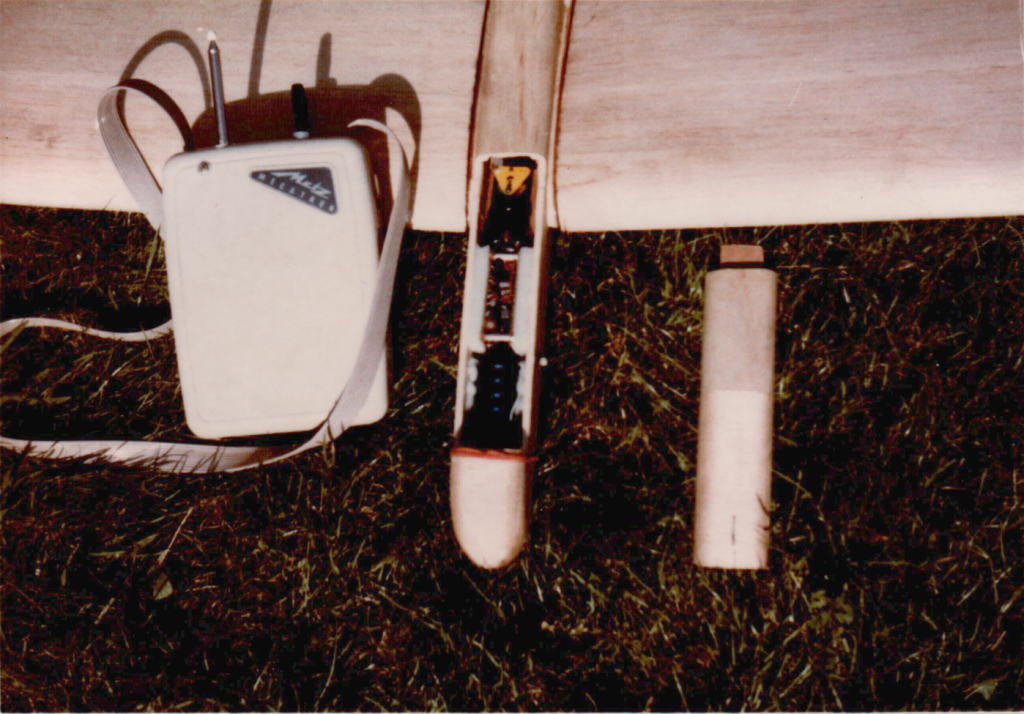
We already had a 3 channel Metz Mecatron radio. But the original receiver was damaged. So I built a new 2-channel RX from a kit offered by the “Reuter” company (doesn’t exist any more). This gave me perfect rudder control. The picture shows the radio installation: A 6 volt DEAC accumulator in the front, followed by the receiver and the Bellamatic servo. There was no elevator control.
The model flew very well and I had a lot of fun with it. At that time my father was a member of the FAG Kaltenkirchen and so I made most of my flights on their Moorkaten airfield. For high start we used 200m of fishing line. The high weight of the model was an advantage in the windy weather conditions of northern Germany.
Additional Pictures:
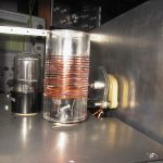
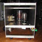
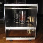
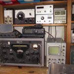
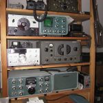
My Regenerative Receiver
Here I want to show you my regenerative receiver:
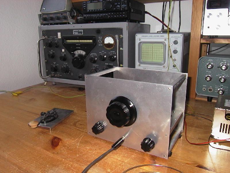
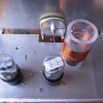
It uses two 12AH7 double triode tubes. They just happened to be available in my junk box.
Here is the schematic: Regen.pdf
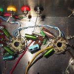
The first two triodes are connected in series, so that they act as a synthetic tetrode. This „cascode“ configuration was discussed in detail by David Newkirk on his excellent website.
The detector circuit presented here was originally used in a receiver that was lent to me by a fellow ham in 1968 when I just started my amateur radio career. It was a kit sold by a German company (Technik-Versand Bremen) and worked perfectly well in those days even on the 10 meter band. I always regretted having given it back so, I wanted to build a replica now. This works even better than the original.
Regeneration is controlled by adjusting the voltage of the second triode’s grid. When the regeneration control is at its minimum position, that means we have 0 Volts at pin 5, there is also no anode voltage at pin 3. The voltage at pin 6 is at its maximum then. When the regeneration control is engaged (voltage at pin 5 increases) the voltage at pin 3 also rises up. At the same time the voltage at pin 6 decreases, because the tube is drawing current and there is a drop across the 100k resistor.
The second 12AH7 works as a two stage audio amplifier. I tried to reduce the number of components to a minimum so, there is no cathode RC-combination in the audio stages. The necessary negative bias voltages are produced by the small grid currents flowing through the 10 MOhm grid resistors (grid leak bias). With my 10 MOhm VTVM I can measure about -0.65 Volts at the grids so, the actual voltage should be about -1.3 Volts. There is no noticeable distortion of the audio signal.
The coupling capacitors in front of the grids are quite small. This helps to reduce the hum. I tried an output transformer in an earlier version (you can still see the slots on the chassis where it was mounted). I hoped to get more audio output this way. But this was a disappointment. So, it was replaced with the original RC-combination (25k/.68µ) shown in the diagram with no ill effects. I can use high and low impedance headphones with good volume. The low impedance ones sound much more „bassy“.
The receiver is very sensitive compared to the pentode circuits I tried before. Using a two feet test lead as an antenna it hears everything on 40m that the R-388 does. Of course, the selectivity is not comparable. But in most cases this is no problem (the selectivity is between the ears of the operator ;-)). Regeneration control is very smooth without any noticeable frequency pulling or hysteresis. But, the regen needs a good ground. In my installation this is a connection to the heating pipe. My shack is located under the roof in the second floor. So, this ground connection is quite long and probably also acts as an antenna. Without this ground the receiver shows severe hand capacity effects and is difficult to tune.
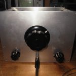
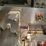
The big center knob drives the band-spread tuning cap. This cap is rather small. I had to remove most of the rotor plates to get a tuning range from 7.0 to 7.2 MHz. It rotates very smoothly and without using a reduction drive tuning in an SSB station is no problem at all. In the lower left you see the control for the band-set capacitor. The knob in the lower right drives the potentiometer for regeneration control.
The plug-in coil is tailored for the 40 meter band where we find a lot of active CW stations here in Germany. It has 18 turns (about 9 µH) with the tap at 5 turns from ground. This tap position needs some more experimentation. I will try to lower the tap to 3 turns so that oscillation starts at a slightly higher voltage at pin 5 of the second triode.
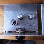
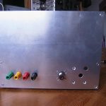
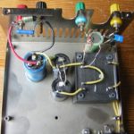
The power supply for my regen is mounted inside the box of a butchered PC supply. I ripped off everything and just kept the case, the AC input socket, the on-off switch and two 330µF electrolytic capacitors. The ‘ugly construction’ works flawlessly ;-). The B+ output delivers about 70 Volts. In spite of the simple circuit, this voltage is quite stable and clean because the receiver draws very little current (about 10mA). Rectification and stabilization of the heater voltage was applied to prevent any hum. The diode in the ground lead of the regulator raises the output voltage to exactly 12.6 volts. Later I added a bleeder resistor of 1 kOhm to the output which is not shown in the diagram.
Additional pictures: